Everything for Electronics

Tech Forum


October 2013

PWM Power and Short-circuit Protection

I'm trying to design a PWM circuit to control power to a resistive heater strip for my camera/telescope. Recently, my nice commercial unit let the magic smoke out after a short on the output side, so I'm not eager to replace it with another of the same make.

The problem is I'm a complete newbie. I'm using a 4093 for the PWM part of the circuit and a pMOSFET (IRF9510) for the power switching. If I didn't want the short-circuit protection, I would be done. I've found a few schematics online but am not sure how to integrate them into my circuit.


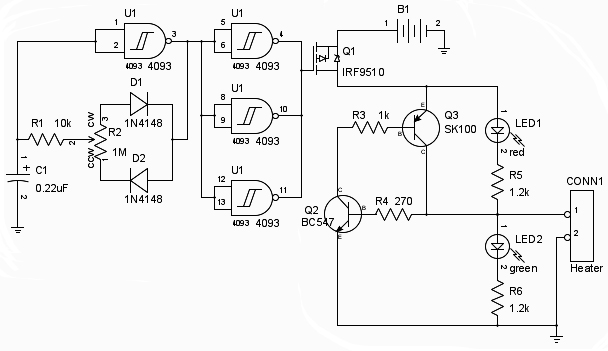
Here's the schematic (Figure 1) I've put together, however, there are two things that bother me. First, I've essentially glued the short-circuit protection onto the output of the pMOSFET which means I have another diode drop in the output. That seems like it should be unnecessary and it seems like I ought to be able to put the IRF9510 where the SK100 is, but I'm not sure how to do that correctly.

Second, the whole thing will be powered off a marine battery and I'd like some input protection/isolation of the control part to avoid the possibility of frying the 4093 from transients when hooking up power.

Any help is greatly appreciated!

#10133
Roland Roberts
Brooklyn, NY

Associated files:


Answers

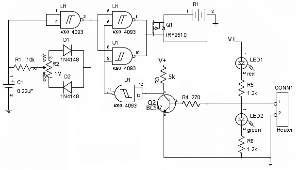
I made some mods to your circuit. With this circuit, Q1 will go directly to the load. With the load there, Q2 will turn on, it's collector will go low. The output of U1-D will be high, so U1-B and U1-C will invert the other input. If the load is shorted, Q2 will be off and the input to U1-D will be high - it's output low. So the inputs to U1-B and U1-C will be low - this will force the outputs high and turns off Q1.

Schneids
Redgranite, WI