Everything for Electronics

Tech Forum


January 2017

Turn Signal Signal

I have a newly restored 1971 Honda CB350 motorcycle that I ride for fun on the weekends. One problem is forgetting to turn off the turn indicators. I have found a kit that “beeps” every time the indicator lights up, but it's very annoying as I sit at a light. I would like a circuit that would alert me only if the turn indicator stays on for more than two minutes. Schematic would be welcome!

#1173
Leland Collins
Gulfport, MS


Answers

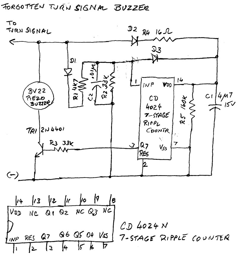
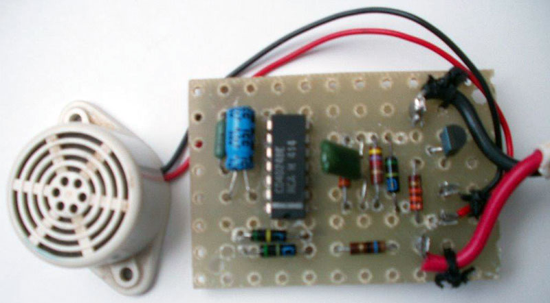
I remembered that I had designed and built a gadget that may be the answer. A hand-drawn page is attached, a bit crude but it says it all.

The piezo buzzer will sound after 64 blinks. Pulsing 12V will charge C1 via D2 + R4 (soften the charge spike). C1 supplies power to the seven-stage ripple counter. It holds enough charge for about three seconds. Pulses are fed to the counter input via D1 and R1. C2 will prevent spikes; R2 will discharge C2; and D2 will prevent input from going higher than Vdd + 0.7V. Output Q7 will go high after 64 pulses. R3 will limit base current to about 0.35 ma – enough to drive TR1 into saturation, but also stretching the discharge time of C1 to about three seconds.

Note that 64 counts is about one minute. If not cancelled, the buzzer will sound for 64 blinks. The next 64 stay silent. When the turn signal is cancelled and left off for four seconds, the count will begin again.

Christian Bock
via email

Sounds like a job for an Arduino Pro Mini and a few discrete parts.

First you need to convert the on-off 12V turn-signal levels from the lamps or LEDs to 5V logic levels. You can find level-shift circuits via a Google search. Then you’ll have two sets of pulses, one from the left signal and one from the right signal. Run the 5V logic signals to two inputs on the Arduino Pro Mini.

Second you need a control program that determines what to do with these pulses and when to turn on an indicator (visual or audible). When the software detects a pulse on either input it starts two timers, Timer1 for 2 minutes and another (Timer 2) for about 1.5 times the length of a turn-signal on-off period (1.5 times the flash duty cycle). Each incoming pulse restarts Timer2. So as long as the Arduino Pro Mini receives turn-signal pulses, Timer2 continues to run. If at the end of the 2-minute period Timer2 is still running, the indicator turns on. The indicator turns off as soon as Timer2 stops running. That indicates no more pulses from the turn signal.

As an alternate, an Arduino Pro Mini could simply count the number of pulses that occur for your vehicle in a 2-minute period and when the count equals that number, it turns the indicator on. You might include a “kill” switch for the indicator in case you need to keep the emergency flasher on for more than 2 minutes. For more information about the Arduino Pro Mini, visit: https://www.sparkfun.com/products/11113.

Jon Titus
Herriman, UT