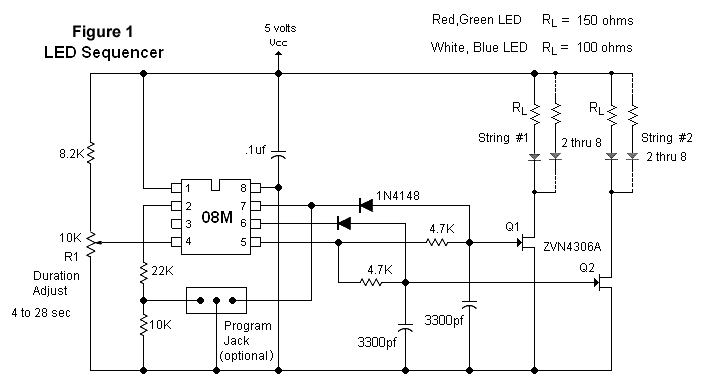
 As far as controlling the LED brightness, here are two possible solutions: one using PWM (pulse width modulation) and the other a variable DC power source. First, I'll describe the PWM circuit in Figure 1 which is controlled by a PICAXE 08M microprocessor. The output from a PWM generator is programmed to run continuously. The timing duration is controlled by the ADC reading on potentiometer R1. The LEDs are controlled by FETs Q1 and Q2. All parameters are set by the programming code.
main:low 1               ' LED set #2 off<br />
     high 0              ' LED set #1 on<br />
     readadc 4, b2       ' read voltage and set duration time, b2 varies from 4 to 28<br />
     let b2 = b2/5 min 4 ' duration time = 500 * b2 * 2<br />
     for w0 = 0 to 500   ' duty cycle scans from 0 to 100%<br />
     pwmout 2,124,w0     ' frequency set at 8KHz, output leg#5<br />
     pause b2            ' LEDs brighten during this for-next loop<br />
     next w0<br />
     for w0 = 500 to 0 step - 1  ' Leds dim during this for-next loop<br />
     pwmout 2,124,w0<br />
     pause b2<br />
     next w0<br />
    <br />
     low 0                ' LED set #2 on<br />
     high 1               ' LED set #1 off<br />
     readadc 4, b2        ' read voltage and set duration time, b2 varies from 4 to 28<br />
     let b2 = b2/5 min 4  ' duration time = 500 * b2 * 2<br />
     for w0 = 0 to 500    ' duty cycle scans from 0 to 100%<br />
     pwmout 2,124,w0      ' frequency set at 8KHz, output leg#5<br />
     pause b2             ' LEDs brighten during this for-next loop<br />
     next w0<br />
     for w0 = 500 to 0 step - 1 ' Leds dim during this for-next loop<br />
     pwmout 2,124,w0<br />
     pause b2<br />
     next w0<br />
     goto main            ' repeat code
Figure 2 uses a combination triangle-square wave generator (U1) to control the variable DC voltage from Q3. R2 controls the duty cycle and R1 controls the minimum DC output from Q3. The setting of R1 will depend on the color and/or type of LEDs used. Basically, R1 is adjusted so the LEDs just shut off before the counter advances. The square wave output (pin7 of U1) is used to advance the 4017 (U2) which is configured as a count to two and recycle counter. The square wave output switches low at each minimum crossing of the triangle generator. This is used to control the "clock enable" (pin 13) on U2. The clock input is connected to Vcc so the counter will advance each time pin 13 goes low. One nice feature about this circuit is the 4017 allows for easy expansion (up to 10) if more LED strings are needed.
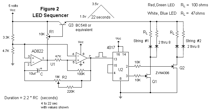
There were no details mentioned about the LED strings regarding how they are wired, the color, or voltage needed. In this case, I decided to show both circuits operated with the LEDs in parallel with individual current limiting resistors. The RL values shown are only guidelines as the specs on the LEDs and the brightness required by the user will vary. Both circuits require a regulated 5 VDC power source.