The Theremin, invented by Leon Theremin (Lev Termen) in Russia in October 1920, was one of the first electronic musical instruments. It's also the very first instrument of any type that you play without touching it in any way. This is the instrument's main claim to fame for those who don't know that much about it, but more importantly, the Theremin is one of the most expressive musical instruments ever built. An expert Thereminist can play as expressively as a violinist or cellist. I have put links to videos of expert Thereminists in the Resources section. Prepare to be amazed!
When Theremin debuted his instrument in America in 1927, he created a storm. If they had had an Internet back then, he would have certainly broken it! It's hard for us to imagine in the 21st century just how shocking and magical the Theremin seemed at the time. The player waved their hands in front of the instrument, and electronic sounds that had never been heard before filled the air. Theremin performed at Carnegie Hall and with the New York Philharmonic, and demonstrated it to Albert Einstein.
Theremin's first instrument was made of valves, and today, Bob Moog (who started by making Theremins before he invented the modern synthesizer) keeps the dream alive with a range of modern Theremins including the beginner friendly Theremini, and the top of the range Claravox concert instrument.
In this article, I'm going to describe how to make a Theremin-like instrument called the LASERVox. The LASERVox, like the Theremin, is an instrument you play without touching it, but uses a completely different technology. The LASERVox, unlike the Theremin, is a perfect project for the novice, because it's a real instrument that can be built very easily with just a handful of components.
You'll see that by using the multicore Propeller FLiP board and some sophisticated LASERPing distance sensors, we can create an instrument that has many Theremin-like qualities and is an expressive MIDI controller. Best of all, it's easy and fun to build and play, and the scope for customization is only limited by your imagination (and the MIDI standard of course!). We'll begin by taking a look at the Theremin because it's the inspiration for and design template of the LASERVox.
What is a Theremin?
Figure 1 shows a photo of my Moog Theremini. This is a good beginner instrument that illustrates the general form of the Theremin quite nicely. Every Theremin has two antennae: a vertical pitch antenna that is played by the right hand; and a horizontal loop volume antenna that is played by the left hand. You can find “Theremin” that have only a pitch antenna, but these are pretty much novelties rather than expressive playable instruments. They can be good for sound effects, however.
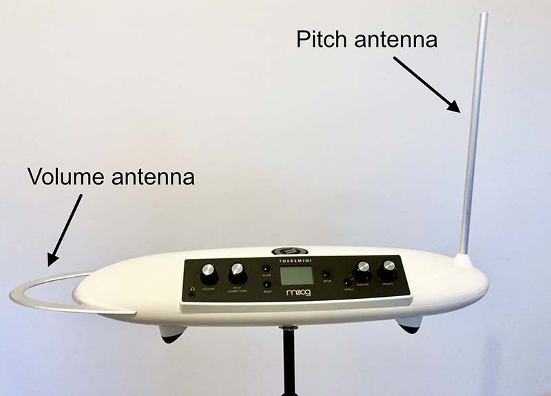
FIGURE 1. Moog Theremini.
Theremin operation is, in principle, simple: As you move your hand in towards the pitch antenna, the pitch gets higher; and as you move your hand down towards the volume antenna, the volume gets lower. Sounds easy until you try it!
Consider the block diagram for a typical Theremin in Figure 2.
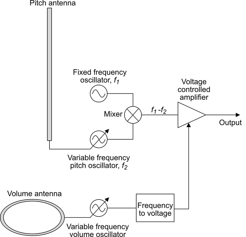
FIGURE 2. Block diagram of a typical Theremin.
The Theremin generates the pitch by heterodyning the output frequencies of a fixed frequency oscillator (f1) and a variable frequency oscillator (f2). Heterodyning is a way of combining two frequencies (f1 and f2) so to generate two new frequencies that are their sum (f1 + f2) and difference (f1 - f2).
As your hand approaches or moves away from the pitch antenna, the capacitance between your hand (at earth) and the antenna changes the frequency of the variable frequency oscillator, f2. The mixer heterodynes f1 and f2 and uses a low pass filter to output only f1 – f2.
In Bob Moog's Theremin design in “Electronic Musician,” February 1996, f1 is set at about 260 kHz and f2 varies between 257 to 260 kHz depending on hand position. This gives the instrument a range (f1 – f2) of about 3 kHz, which is up to about G7 on the piano.
The volume control circuit works slightly differently. The volume antenna also uses capacitance with your hand to control the frequency of the variable frequency volume oscillator. However, this frequency is then converted into a voltage that controls the voltage-controlled amplifier that is part of the output stage of the instrument.
The Theremin block diagram looks simple, but in practice, Theremin circuits are sensitive, complex, and hard to build. This is where the LASERVox comes in!
What is the LASERVox?
My LASERVox is shown in Figure 3. The most obvious difference between the LASERVox and the Theremin is that the LASERVox substitutes a combination of a LASERPing time-of-flight distance sensor and 24 element LED ring for both the pitch and volume antennae. We will see how these work shortly. Notice that the LASERVox maintains the reverse L shape of a typical Theremin.
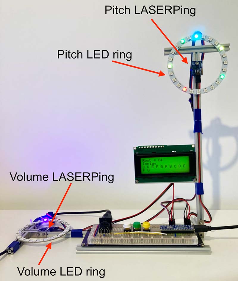
FIGURE 3. The LASERVox. Note the arrangement of the pitch LED rings and sensors. These are equivalent to the Theremin pitch and volume antennae.
The LASERVox is not a Theremin. It's a MIDI Laser Theremin. I think because you play it without touching it, it certainly fits in the class of Theremin-like instruments. Both are electrophones (according to the Hornbostel-Sachs instrument classification scheme) and both have the distinctive characteristic of being played without touching, so they are definitely taxonomically related, although clearly not identical. The essential differences between the LASERVox and the Theremin are:
1) Technology: The LASERVox uses time-of-flight distance sensors to control pitch and volume, not heterodyning oscillators. The pitch sensors are the excellent LASERPing time-of-flight distance sensors from Parallax.
2) Sound: The LASERVox makes no sound of its own — it's a MIDI controller. It just outputs MIDI data that is made into sounds by a synthesizer.
3) Pitch Quantization: The LASERVox is pitch quantized because MIDI is pitch quantized. This makes it easier to play in some cases (try the blues scale!). The Theremin outputs a continuous range of pitches and you need a good ear and/or an electronic tuner to find the notes in a scale. I should point out that the Moog Theremini is a Theremin that has variable pitch quantization that allows you to control the degree to which a pitch will lock on to the nearest note in your chosen scale. This makes it an excellent beginner's instrument because you can get a tune out of it quite easily with quantization on, and still learn real Theremin technique by slowly reducing quantization until it is off.
4) Sensitivity: The Theremin is an exquisitely sensitive instrument that interacts via the electromagnetic fields around its antennae with the player, the room, and the humidity of the air — essentially with any conductive body within its field of action. The LASERVox is only sensitive to the distance between the sensors and the player's hands.
5) Calibration: The Theremin must be recalibrated if it's moved or its electromagnetic environment is changed in any way because the positions of the notes within the field around the pitch antenna move. The LASERVox has rock-solid pitch location. You place the pitches precisely where you want in the space in front of the sensors and that is where they will stay. A related point is that the Theremin pitch locations tend to be non-linear and the pitches get closer together the nearer you are to the pitch antenna. The LASERVox is completely linear, unless you program it otherwise.
6) Complexity: A good Theremin has complex, sensitive, finely-tuned analog circuitry. As you will see, the LASERVox has simple digital circuitry that is pretty much bullet-proof, and can be built on a solderless breadboard in about half an hour.
Obviously, these are two different instruments. If you want an instrument with violin levels of sensitivity, then the Theremin is for you. If you want an instrument that is easier to play and that can control your MIDI synthesizer, then that is precisely what the LASERVox offers. They have the shared characteristic of being completely contact-free! I think the two instruments complement each other, and I hope you will get the Theremin bug from the LASERVox and progress to a more sophisticated instrument. Similarly, I hope experienced Thereminists might find the LASERVox a fun way to control MIDI devices.
How the LASERVox Works
I'm not going to present a block diagram for the LASERVox because the actual circuit (which is shown in Figure 4) is simplicity itself. An important point to note is that the circuit operates at 3.3V apart from the WS2812 LED rings and the Parallax serial LCD, which need 5V. Because of the 5V components, the FLiP must be powered from the micro-USB port!
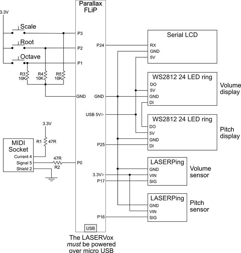
FIGURE 4. LASERVox circuit diagram.
The FLiP provides 3.3V power via an onboard regulator on its 3.3V▷ pin. However, it will only offer 5V on its USB 5V▷ pin when it is powered from its micro-USB port! This is because there is no onboard 5V regulator and the 5V on this pin comes directly from the USB connection. Because the LASERVox needs 5V for some components, you must always power it via its USB port. You can't use a 9V battery or an external 5V to 9V power supply.
The heart of the LASERVox is the Parallax FLiP. This is an easy-to-use development board for the immensely powerful Parallax Propeller multi-core microcontroller. I discussed the Propeller and the FLiP board in some depth in my previous article, “Parallel Processing with the Propeller FLiP” in Nuts & Volts (see Resources). Essentially, each Propeller chip has eight identical 32-bit cores that run in parallel (see Figure 5).
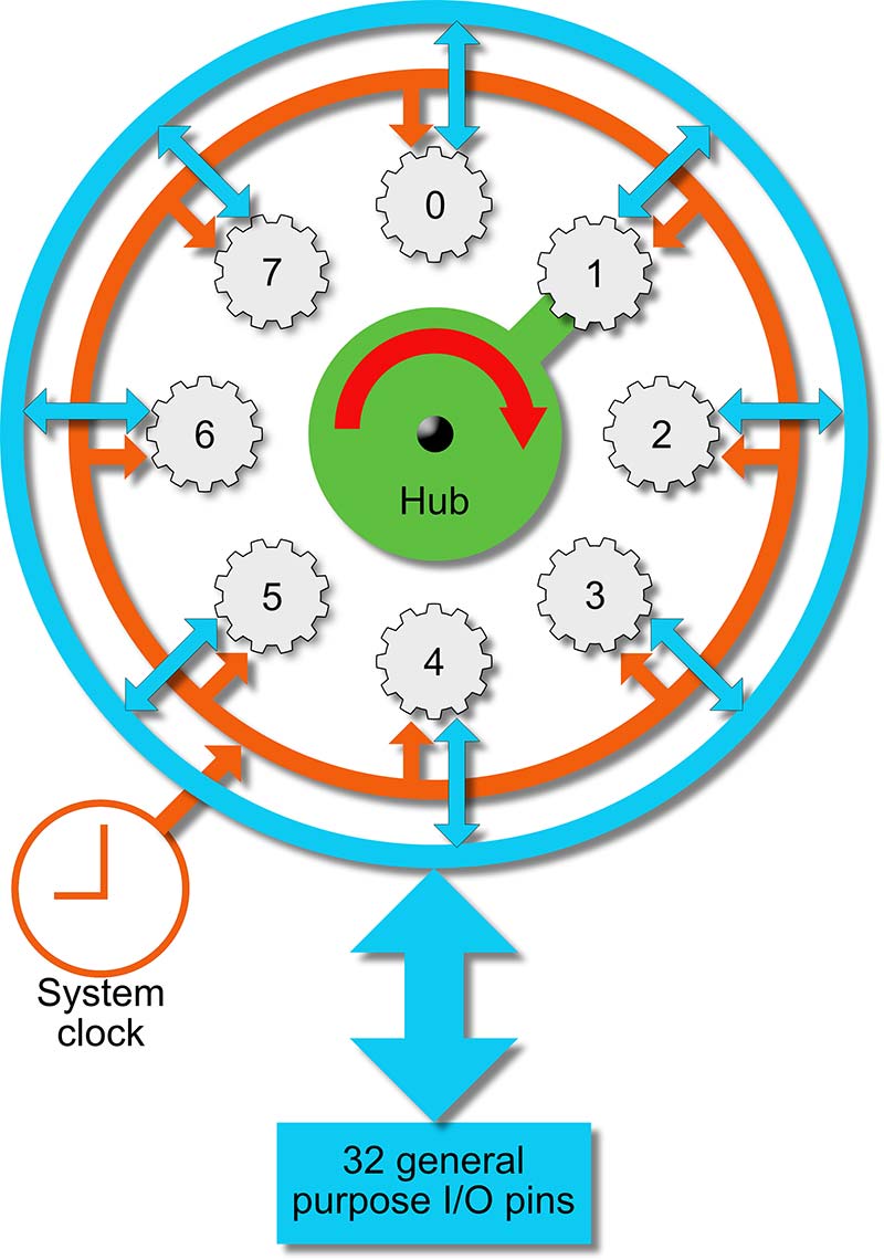
FIGURE 5. The Propeller chip block diagram.
The central hub cycles through the cores offering each of them sole read/write access to the hub resources for one clock cycle. This means that cores can share data without any resource contention issues, provided they can do what they need to do in one clock cycle. If they can't (for example, if they're accessing a peripheral that requires multiple clock cycles), then a core can open a lock on the hub resources until it's finished. This makes parallel processing on the Propeller about as simple as it gets! There's no need for interrupts because you have true parallel processing that enables you to assign tasks that need to run in parallel to their own core, and resource contention issues are greatly reduced because of the elegant hub architecture.
The key peripherals that make the LASERVox possible are the Parallax LASERPing distance sensors. These measure the time of flight of a pulse of infrared laser light that is bounced off the target which, in this case, is the musician's hand. The sensors have millimeter accuracy and a 22 Hz refresh rate which is quite adequate for our purposes.
There is one sensor to control pitch (connected to FLiP P16) and another to control volume (FLiP P17). The times of flight sent to the FLiP by the sensors are converted into MIDI notes and volumes by the LASERVox software, which we will look at shortly.
The MIDI data is output on FLiP P0 to the MIDI Out socket via a 10R to 100R resistor that protects against short circuits in cables or equipment. All this operates at 3.3V and is the heart of the LASERVox. In fact, you can make a very simple LASERVox with just these components.
The final 3.3V components are the pushbuttons: one to select the scale (on P3); one for the root of the scale (on P2); and one for the octave (on P1). Notice that there are pull-down resistors on the FLiP pins. This is because when Propeller pins are set to input, they float. As they say, the devil makes work for idle hands, and if you don't pull them up or down, they will tend to do their own thing and oscillate. The 5V part of the circuit begins with the two WS2812 24 LED rings that are used to indicate pitch and volume. Each of the 24 RGB LEDs in these rings is individually addressable and may be set to about a million different colors. The rings operate at 5V and each LED (when fully lit) takes about 10 mA.
The DI (data in) of the pitch ring is driven from FLiP P25, and the two rings are daisy chained together, with the DO (data out) pin of the pitch ring connected to the DIN (data in) of the volume ring. Because they are daisy chained, the rings appear to the software as a single array of 48 LEDs, of which the first 24 are in the pitch ring and the last 24 are in the volume ring. The 5V power for the LED rings is available on the FLiP USB5V pin. As I said earlier, this comes from the USB port, so the LASERVox must be powered via micro-USB.
The only other part of the 5V circuit is the Parallax serial LCD. This device is driven by a serial port on FLiP P24 and is used to display the tuning (scale, root, and octave). It's also powered from the FLiP USB5V pin. For more details, you can find datasheets for all the Parallax components on the Parallax website. (There are links in the Resources section.)
As you can see, the LASERVox circuit is pretty simple. However, it's still a good idea to assemble it methodically in stages. We'll look at how to do this once we have set up the development environment.
Setting Up the Development Environment
I originally planned to develop the LASERVox software using the BlocklyProp graphical development environment that I discussed in my previous Propeller article (see Resources).
However, at the moment, BlocklyProp is incompatible with MIDI (and other serial protocols) because its serial block only writes null terminated strings and not bytes. I've raised this with Parallax, and there may be a fix by the time you read this.
This leaves us with two other possible development environments: Spin and C. I decided to use C because many of you will already be familiar with it. I hope to cover Spin in a future article, where I can do it justice.
First, you need to download and install the SimpleIDE integrated development environment from Parallax (see Resources). You'll find installers and instructions for Windows, Mac, Linux, and the Raspberry Pi. Once you have the software installed and running, you should see a window like the one in Figure 6.
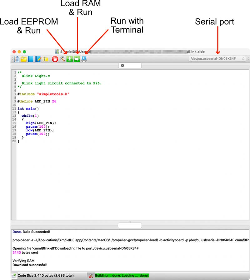
FIGURE 6. Parallax SimpleIDE.
SimpleIDE is project based, so to do anything with it, you have to create or load a project. You can manipulate projects from the toolbar (the first five buttons) or from the menus. There are five key things to note about SimpleIDE:
1) The Serial Port Dropdown. This is where you select the serial port that your FLiP is connected to. You can't load software to the FLiP unless the right serial port is chosen. On the Mac, this is usually trivial, because there is typically only one entry in the list. On other platforms, there may be several to select from. The dropdown may be empty until you plug in a FLiP. If you power cycle your FLiP by disconnecting the micro-USB, you will have to select the serial port again.
2) Load to RAM & Run. This is the normal option during development and testing. It compiles your code and loads it to the FLiP RAM. This is a very quick process, but if you power cycle the FLiP, the code will be lost.
3) Load EEPROM & Run. This is the option when you have finalized your code. It's compiled and loaded into the FLiP EEPROM where it is persistent. This takes a bit longer than Load to RAM & Run because it's writing to EEPROM. When the FLiP is power cycled, it will boot to this code.
4) Run with Terminal. This is exactly the same as Load to RAM & Run, except that it opens the SimpleIDE terminal. You can print to this from within your C programs. Note that the terminal window has a nasty habit of popping up under existing windows! You may need to search for it.
5) Getting Help. SimpleIDE has a comprehensive help system under the Help menu. In particular, you should take a look at the SimpleIDE User Guide, the Propeller C tutorials, and the Simple Library Reference. The Simple Library is where you can find all the Propeller C code for working with serial ports, peripherals, etc.
Once you're familar with SimpleIDE, the next step is to download the LASERVox code from the downloads for this article. Unzip the file into a convenient directory. You'll find that there are several projects in the zip file, and we'll use all of them as we develop the LASERVox.
Testing the Development Environment
We can now test the development environment:
1) Plug the FLiP into the bottom of a full-size solderless breadboard (see Figure 7) and connect it via its micro-USB to your computer via a USB hub for safety. A green LED next to the power symbol (above P8) should light up telling you that your FLiP is ready to go.
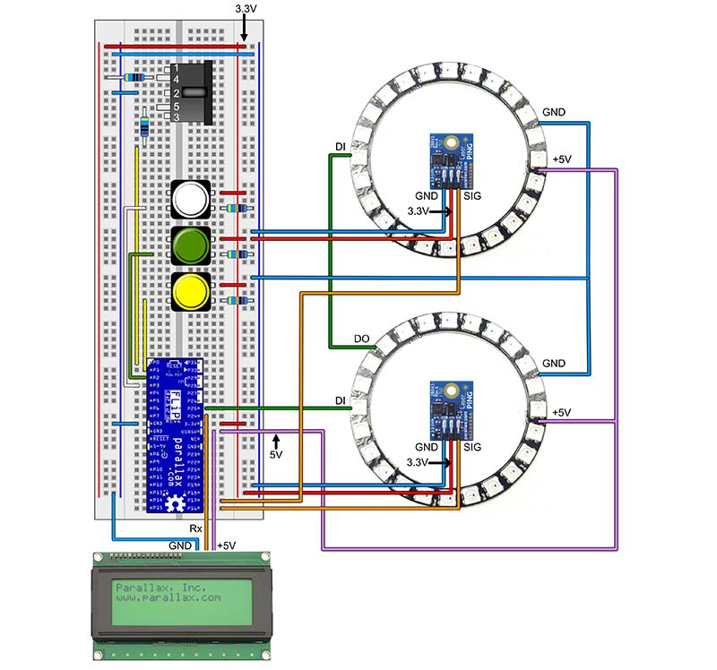
FIGURE 7. Breadboard layout.
2) Ensure the serial port for the FLiP is visible and selected in SimpleIDE. If you have problems making a serial connection, it might be your micro-USB cable. Some cables are designed for charging only and don't have a full complement of wires for data transfer. There's no easy way to tell the difference apart from trial and error.
3) In SimpleIDE, select the menu Project/Open or use the toolbar, and open Blink.side from your LASERVox code directory. The FLiP board has a built-in LED connected to pin 26. Download the code to the FLiP RAM, and you should see the LED blink.
If everything works, we are good to go! If not, check everything is plugged in and that you have selected the right serial port. SimpleIDE should warn you if there are any problems. You might try modifying the blink time in the code, just to get a bit more used to SimpleIDE. Now that the development environment is set up, we can look at how to build the LASERVox.
Connecting the FLiP and Powering the LASERVox
As I mentioned above, for safety it's always best to connect a development board such as the FLiP to your computer via a USB hub.
The LASERVox will take quite a bit of power, so you really need a powered USB hub for this project. Each of the 48 LEDs in the LED rings can consume up to 50 mA when set to full brightness at 5V. We'll have up to eight of these LEDs illuminated at any one time, which gives us a worst-case power consumption of 400 mA just for the LEDs.
The LCD panel takes about 80 mA when illuminated. Each of the LASERPing sensors requires 25 mA and the FLiP itself takes some power, depending on what it's doing. When you have finalized your build and you want to use your LASERVox stand-alone, you'll need a 5V micro-USB power supply that can deliver at least 2.5A. Raspberry Pi power supplies seem to work well, and you can get these with an inline switch in the cable, which is very convenient. You need to be very careful here. You need a 5V micro-USB power supply not a micro-USB charger! This is because chargers have complex circuitry to manage the power to the devices they're charging. Generally speaking, they will not work well with something like the LASERVox that draws a lot of current, and you should avoid them.
Should you modify the LASERVox to use more illuminated LEDs, you need to be aware that the FLiP takes 5V power from the micro-USB via a USB current limiter and fault detection circuit. The FLiP can source a maximum current of 1,500 mA summed across all its pins. Any more than this, and the FLiP fails safe, illuminating an amber warning LED to alert you to the problem. You can get around this limitation by adding an external 5V power supply specifically for the LEDs if you need to. With our power requirements sorted out, we are ready to go!
Construction of the LASERVox
I built the LASERVox on a full-size solderless breadboard. Figure 7 shows a suggested layout. Although the circuit is simple, it's best to proceed in a methodical manner because there's quite a lot of point-to-point wiring and it's easy to get this wrong. I've supplied test programs so that you can build the circuit in stages and test as you go. In fact, each of these test programs can be considered a fun mini project in its own right! IMPORTANT: Always remove power (the micro-USB connector) before making changes to the breadboard or wiring.
Mechanical Assembly
Usually, I would describe constructing the electronics, getting it working, and then you would put it in a box or mount it on a board or something. In this case, because there is a lot of point-to-point wiring and solderless breadboard connections are notoriously easy to pull out, you'll do yourself a great favor if you first mount the board and all the off-board components securely on whatever frame you're going to use for the instrument, or on a temporary frame.
I built the frame for my instrument using extruded aluminum from MakerBeam (see Resources). This is a construction kit for makers that allows you to create all kinds of frames for electronics, robots, and so on. It's a very flexible system that's easy to use and perfect for projects such as this. However, provided you position the LEDs and sensors as I will describe, there's no reason why you shouldn't build the frame out of wood. I came across another maker construction set recently called the Totem Maker Kit (see Resources). I haven't tried it yet, but it looks promising.
Looking at my LASERVox back in Figure 3, you can see that it's essentially a right angle with a horizontal volume LED ring and sensor (corresponding to the Theremin volume antenna to the left) and a vertical pitch LED ring and sensor (corresponding to the pitch antenna to the right).Whatever method of construction you use, the key mechanical requirements are:
1) Each LED ring and sensor should be treated as a unit, with the sensor mounted in the center of the ring. For the pitch ring, LED 0 should be at the top. For the volume ring, it doesn't really matter that much.
2) Volume and pitch sensors should be separated by about 25 to 30 cm horizontally and about 25 to 30 cm or so vertically.
3) The breadboard should be mounted roughly halfway between the ring/sensor units to keep wiring as short as possible.
4) The LCD should be mounted somewhere close to the buttons.
5) There should be a way to secure the MIDI cable because the MIDI socket is not very secure on the breadboard (you could also use a secured off-breadboard socket).
6) All point-to-point wiring should be well secured with cable ties or insulating tape.
For a Theremin style instrument, the critical aspect of the construction is that the pitch LED ring/sensor is vertical and the volume LED ring/sensor is horizontal as in Figure 3. Of course, you don't have to build a traditional Theremin style instrument! Another option is to place both volume and pitch LED ring/sensor units in either the horizontal or vertical planes. I haven't tried this, but I suspect that it might make the instrument more difficult to play.
Assembling the Breadboard
As I mentioned, there's a suggested breadboard layout in Figure 7. Start by connecting the power rails on both sides of the breadboard as shown; + to + and - to -. Insert the FLiP at the bottom of the board (if you haven't already done so) and connect the GND under pin 7 to the negative rail and the 3.3V▷ pin to the positive rail. Plug in the FLiP micro-USB and check you have 3.3V power on both sides of the breadboard. The FLiP is quite a forgiving board, and if there's a problem with its power, it will often indicate this by illuminating the amber LED above and to the right of the micro-USB under the ! symbol.
Assembling the MIDI Output
Next, wire up the MIDI socket. Pay careful attention to the pin numbering which is shown in Figure 8. FLiP pin 0 is the MIDI output, and this goes via a 10R to 100R resistor to MIDI socket pin 5 (Signal). Pin 4 (Current) of the socket goes via a 10R to 100R resistor to 3.3V and pin 2 (Shield) goes to GND. Check this wiring carefully because the MIDI socket pins have a rather strange numbering scheme! Connect your MIDI synth.
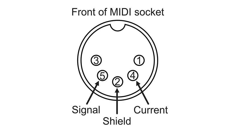
FIGURE 8. Front view of the MIDI Out socket.
Load the MIDITest.side project file into SimpleIDE and write it to your FLiP's RAM. The test program plays the three-part round, “Viva La Musica,” by Michael Praetorius (1571 to 1681). Each part is played by a separate core. The program illustrates how to use Propeller locks to stop the cores from stepping on each other when they try to write to the shared MIDI serial port. If your MIDI output doesn't work, the most likely problems are that you have connected to the wrong FLiP pin, or you have Current and Signal the wrong way around on the MIDI socket.
Buttons
Next, wire up the three buttons and pull-down resistors on the FLiP pins:
1) Pitch button -> FLiP pin 3
2) Root note button -> FLiP pin 2
3) Octave button -> FLiP pin 1
Load the ButtonTest.side project into SimpleIDE and download to the FLiP with the “Run with Terminal” option. Press each button in turn, and you should see the numbers and notes in the terminal increment on each button press and then wrap around to zero. If it doesn't work, check your wiring. If you're using the recommended tactile buttons, then check which of the four pins on the bottom of the button are connected together and which form the actual switch. The swich is normally between the pins that are closest together.
LASERPings
Now we get to the fun bit — you can connect the LASERPing sensors! As I already mentioned, you should first decide on how you're going to build your LASERVox because it really is much, much easier if the breadboard and sensors are firmly secured before you connect them.
Connect the pitch LASERPing sensor SIG pin to FLiP P16 and the volume LASERPing sensor SIG pin to FLiP P17. Both sensors should also be connected to 3.3V power and GND. Load the LASERPingTest.side project into SimpleIDE and download to the FLiP with the “Run with Terminal” option. Move your hands in front of the sensors, and you should see numbers changing in the terminal. These numbers are the time of flight in Propeller chip system click ticks for a laser pulse to bounce off your hands. If you want to change the distance calibration of the LASERVox, you can use this test program to convert distances to Propeller chip system click ticks.
LED Rings
This is the 5V part of the circuit. Each ring should be mounted so that it has a LASERPing in its center. Ensure that the positive terminal of each ring is connected to the FLiP 5V USB pin and the negative terminal to GND. The DI (data in) of the pitch ring is connected to FLiP P25. The DO (data out) of the pitch ring is connected to the DI (data in) of the volume ring, creating a daisy chain.
Load the LEDRingTest.side project and download to the FLiP RAM. You should see some illuminated LEDs travel around each ring. If you don't see this, check the power connection to the rings, check the daisy chain, and check that DI of the pitch ring goes to FLiP P25.
For a bit of fun, I have combined the test programs for MIDI and LEDs into the MIDILEDTest.side project. This will play Viva La Musica while also illuminating the appropriate LEDs. It demonstrates how the full duplex serial and WS2812 interface objects use cores, and how you can find the ID for a core and use that in your program.
Serial LCD
This last part of the 5V circuit is the final part of the LASERVox. The Parallax serial LCD is a really useful device because it accepts normal serial communications over a single wire. This allows you to add an LCD to your project using only three wires. However, the LCD is not quite as forgiving as some of the other components, and the datasheet indicates that you must always have 5V power on the LCD whenever there is a signal on its RX input. Otherwise, damage might result. First off, set the baud rate of the LCD to 2400 baud as shown in Figure 9.
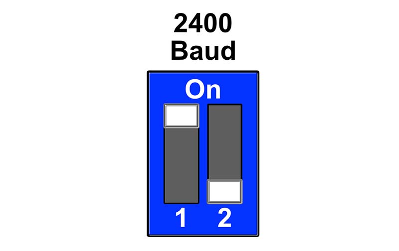
FIGURE 9. Set the LCD switches to 2400 baud.
Connect the 5V pin of the LCD to the FLiP 5VUSB pin, and the GND pin to breadboard GND. Connect the RX pin (serial input) of the LCD to FLiP P24. Load the LCDTest.side project and download to the FLiP RAM. The LCD should light up and some messages should be displayed. If nothing happens, check the power to the LCD; check that LCD RX is connected to FLiP P24; and check the LCD baud rate switches are set for 2400 baud.
Loading the LASERVox Software
You can now load the LASERVox software. Load LASERVox.side into SimpleIDE and download to FLiP RAM. If you have gone through the construction process outlined above, then everything should just work. You can play notes on the pitch sensor, control volume with the volume sensor, and select scales, roots, and octaves with the buttons. Everything should be displayed on the LCD panel.
Once you're happy it all works and you have made any tweaks you desire, you can then download it to your FLiP EEPROM. In the next few sections, I'll discuss various aspects of the LASERVox software.
The MIDI implementation
MIDI (Musical Instrument Digital Interface) is, among other things, a simple serial protocol for controlling synthesizers. You can find out all about MIDI by visiting the MIDI Association website (see Resources). This protocol has been around since 1981 and has been astonishingly successful. MIDI has empowered millions of musicians and instrument makers all over the world. The LASERVox outputs MIDI messages over a serial port at 31250 baud to control your MIDI synthesizer. MIDI messages are a sequence of two or three bytes. The first byte is a Status Byte, that is divided into two nibbles (four bits). The most significant nibble indicates what the message means, and the least significant nibble indicates the Channel Number (0 to 15).
Any synthesizer can be programmed to only respond to messages on a particular channel, but most synthesizers default to Omni Mode, so they respond to messages on every channel. The LASERVox sends on Channel 0, but this can be changed by editing the noteOn() and noteOff() functions.
After the Status byte, the rest of the message contains one or two Data Bytes depending on the message. There are only three MIDI messages that we need to be concerned with for the LASERVox, and these are shown in Table 1.
| Note On |
| Status byte, Note On |
Data byte 1, Note |
Data byte 2, Velocity |
Description |
| 1001 0000 to 1001 1111 |
0000 0000 to 0111 1111 |
0000 0000 to 0111 1111 |
Turns the specified note on. |
| 144 to 159 |
0 to 127 |
0 to 127 |
|
| Note Off |
| Status byte, Note Off |
Data byte 1, Note |
Data byte 2, Velocity |
Description |
| 1000 0000 to 1000 1111 |
0000 0000 to 0111 1111 |
0000 0000 Usually ignored |
Turns the specified note off. |
| 128 to 143 |
0 to 127 |
0 to 127 |
|
| Channel Volume |
| Status byte, Control Change |
Data byte 1, Function |
Data byte 2, Volume |
Description |
| 1011 0000 to 1011 1111 |
00000111 (Channel Volume) |
0000 0000 to 0111 1111 |
Changes the master volume of the synth. |
| 176 to 191 |
7 |
0 to 127 |
|
TABLE 1. MIDI messages used by the LASERVox.
For each of the messages, the table shows the Status Byte and any Data Bytes. For the MIDI Note On and Note Off messages, the Status Byte specifies the message type and the channel. The first Data Byte is always the MIDI number for a note. This is a value from 0 (C-1) to 127 (G8). This mapping assumes that C4 (middle C) = 60 MIDI, which is the case for most synthesizers. The second and last Data Byte is a velocity from 0 (silent) to 127 (maximum).
For Note On, the velocity usually determines the attack for the note, which determines its initial volume. Velocity is generally ignored for Note Off messages and is usually set to 0, but some sophisticated synths may use this parameter to control timbre or some other parameter of the note as it's released. The Channel Volume message has a somewhat different format. The Status Byte says that this is a Control Change (CC) message on a particular channel. The second byte says that the CC function selected is Channel Volume, and the final byte is the actual volume to set, where 0 equals silent and 127 equals the maximum volume of the synthesizer.
A key point is that once a note has been assigned an initial velocity in Note On, Channel Volume can only decrease it. It actually took me a little while to figure that out! This means that in order for the left hand to have control over a full range of volume, the LASERVox must sound every note with the maximum velocity of 127. To do this, the LASERVox has to send MIDI messages as follows:
When a new note is selected:
1) Turn off any already playing note with Note Off.
2) Turn on the currently selected note with Note On, velocity 127.
3) Turn the volume down to the currently selected volume with Channel Volume.
This gives us a very expressive instrument, where the left hand can control the volume of a note as it's playing, allowing for swells, crescendos, decrescendos, tremolo (rapid small changes in volume), and so on. See to Table 1.
LASERVox Tuning
A real Theremin outputs a continuously varying pitch, so tuning is a moot point. The LASERVox, however, outputs MIDI Note On and Note Off messages so its output is necessarily pitch quantized. This means that instead of outputting a continuous sweep of pitch (like a Theremin), it generates individual pitches which are the notes in a scale.
Note that it's possible to approximate a continuous sweep of pitch in a MIDI synthesizer by creative use of Pitch Bend MIDI messages. However, there is no general solution because synthesizers can interpret Pitch Bend differently even on a voice-by-voice basis. You might get it working for one synth/voice, but it wouldn't work on another. At some point, I might consider designing a LASERVox with its own built-in MIDI synthesizer, so that it can offer continuous pitch sweep as well as MIDI output.
The LASERVox has a range of 12 notes. This is because there are 24 LEDs in the pitch ring, and there needs to be an LED between each note to indicate when you are off the pitch.
I have given the LASERVox a useful selection of scales summarized in Table 2. Each scale has 12 notes, and I have listed the pattern of intervals (see later), the MIDI note offsets, and an example generated scale with C as the root. I've also indicated the notes that are highlighted on the pitch LED ring.
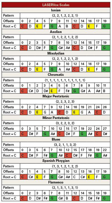
TABLE 2. LASERVox scales.
Take a look at Table 2. The root is red, the third is yellow, and the fifth is green. This highlighting is very important because it helps you know where you are in a particular scale. The LASERVox allows you to select a scale, a starting note, and an octave, allowing you to play in any key in any octave. It's worth delving into a little music theory in order to understand how to create scales for the LASERVox. All scales in the Western tradition are constructed by dividing the octave into a sequence of intervals. The two most common intervals are the tone (t) and the semitone (s), where t = 2s.
The smallest interval is the semitone. There are 12 of these in an octave; one for each note of the chromatic scale. They all sound the same “size,” so the octave is equally divided into 12 semitones. This is known as 12 Tone Equal Temperament (12TET; see Resources). Other temperaments are available.
Every interval can be expressed as a number of semitones (a multiple of s). This means that it's possible to specify a scale as a sequence of intervals from one note to the next. For example, the Ionian scale has an interval pattern ttsttts that can be expressed in terms of semitones as 221221. We can now calculate with the scale and, in particular, generate the sequence of MIDI numbers for the scale on any root.
Let's look at an example: the Major scale on middle C. This is C4 Ionian, and it has the interval pattern 2212221 and root C4. We can easily convert this into a MIDI number as follows:
1) Take the MIDI number of the root. Middle C is C4, which is 60 MIDI.
2) Apply the scale pattern starting at 60: 60, (60+2), (60+2+2), (60+2+2+1), (60+2+2+1+2), (60+2+2+1+2+2), (60+2+2+1+2+2+2), (60+2+2+1+2+2+2+1) = 60, 62, 64, 65, 67, 69, 71 = C4, D4, E4, F4, G4, A4, B4 = C4 Ionian.
This is the way to generate scales for the LASERVox. Simply find the interval pattern for the scale and apply it as shown above. You can generate any 12TET scale in this way. I've provided three modes of the major scale: the Ionian mode (the major scale itself); Aeolian mode (natural minor); and the Mixolydian mode. The other modes are not so useful, so I haven't bothered. The major and minor scales are obviously necessary, but the Mixolydian mode needs a bit of explaining. Mixolydian is a particularly useful mode if you don't have many notes to work with. Consider a 12 note Mixolydian mode scale. It has an Ionian mode scale embedded in it starting on its fourth degree. Consider G Mixolydian as an example:
G A B C D E F G A B C D
You can see that it starts at the G below the first C of a C Major scale. Given that many Ionian mode tunes start one to three notes below the root, you can see why this is very useful! Obviously, if your instrument has many notes, then this isn't an issue. However, if you only have 12 notes (as the LASERVox does), then this mode allows you to play tunes that might be impossible otherwise.
In fact, Mixolydian mode is usually a great option for folk instruments. Appalachian Dulcimers are often in Mixolydian mode, and I also used it for my MIDI Lyre project that was published in Nuts & Volts (see Resources).
When using Mixolydian to access Ionian mode, just remember that if you want an Ionian scale with a root of X, you have to start the Mixolydian scale at X-3. I've also provided a range of non-modal scales. These have tone/semitone patterns that are not cyclic permutations of the modes, and some have wider intervals than a tone. Of particular note are the pentatonic and blues scales. You just can't go wrong with these because all the scale notes sound great together. They are perfect for improvising!
Of course, it's possible to add your own scales to the LASERVox. I've provided a link to a table of scales and modes in the Resources. I've also tried to document the C code as clearly as I can to show you how to add (or remove) scales. Of course, you don't have to program scales. You have 12 notes to play with, so how about a 12-note tune or bassline that you play just by moving your hand towards the sensor. I was going to say, “the possibilities are endless,” but, in fact, there is a choice of 128 possible MIDI notes for each of the 12 slots, which gives us exactly 12,812 = 19,342,813,113,834,066,795,298,816 possibilities!
LASERVox Software
The LASERVox software is quite liberally commented, so if you know some C, it shouldn't be too difficult to follow. First, I'll say a bit about how scales are implemented in the software, so you can add your own if you want to. The scale itself is represented in the Scale structure:
typedef struct Scale{
char name[20];
int root;
int *offsets;
int *hilights;
} Scale;
The members of this structure have the following meanings:
- Name: A slot for a 20-character name.
- Root: The starting MIDI number for the scale.
- Offsets: An integer array of 24 offsets that when added to the root gives us the scale.
- Highlights: An integer array of 24 LED colors that are the pigment for the scale.
We calculate the MIDI notes for a scale by adding the offsets to the root. For convenience, the offsets and highlights arrays have 24 elements — one for each LED in the pitch ring — even though there are only 12 notes in a scale. Here's an example of the offsets array for the Ionian mode:
int ionianOffsets[] = {0,X,2,X,4,X,5,X,7,X,9,X,11, X,12,X,14,X,16,X,17,X,19,X};
You can see that there are 24 elements; one for each LED in the pitch ring. Every other element is a valid offset, giving us 12 notes separated by non-notes (X). We map the distance from the pitch sensor to a range of 0 to 23, giving us an index into this array. If the index points to a valid offset, we light the appropriate LED blue, add the offset to the root to get the MIDI number of the note, and output that note. If it points to X, we are between pitches, so we don't output a note but we do light the appropriate LED orange. There is some additional housekeeping, turning off any already playing note and so on, but in essence, this is how the LASERVox software deals with scales. All the scales are stored in an array called scales, and NUM_SCALES must contain the number of scales in this array. Now that you understand the Scales data structure, we can look at how the program operates.
Core 0
The main() program runs in core 0. It does some housekeeping (sets up the scales and so on) and then creates three objects to manage the peripherals (Table 3).
| Object |
Lock |
Description |
| lcd |
N/A |
A full duplex serial object to control the serial LCD panel. This has no lock because it is only ever accessed from the same core. We use full duplex (even though we are only sending) because the half duplex library only works from the main core. |
| midi |
MIDILock |
Another full duplex serial object to output the MIDI messages. |
| leds |
LEDLock |
An object to control the WS2812B smart LED rings. |
TABLE 3. Peripheral objects.
After creating the objects to manage the peripherals and their associated locks, the main() program launches three cores by using cog_run(...) on the following functions:
1) getVolume(): the Volume Core
2) getPitch(): the Pitch Core
3) getButtons(): the Button Core
It then goes into an infinite loop because all the rest of the work is done in the cores. Because this is a multi-core program, we need to think a bit about resource management. If a resource needs to be shared between cores and it can be manipulated in a single clock cycle, then there's nothing that needs to be done because each core gets exclusive access to the hub resources for one clock cycle as the hub “rotates.” This is the case for global variables that are integers or integer arrays.
The objects managing the peripherals are more complex and require several clock cycles to do their job. If such an object is shared between cores, then each core must be sure not to step on the toes of any of the others. This is accomplished by a simple lock mechanism.
The core sets a lock, performs its actions on the object, then releases the lock when it has finished with the object. Each core must wait until the lock is released before it can get the lock for itself. This is a very simple and elegant mechanism for dealing with resource contention. I've provided an example of the use of locks in the MIDITest.side project.
Considering the objects managing the peripherals: The LCD is only accessed from a single core (the Button Core; see later), so the lcd object doesn't need a lock. The midi object is accessed by both the Volume and Pitch cores, so it needs a lock; similarly with the leds object.
Next, we'll consider each core.
The Volume Core – getVolume()
This core is responsible for:
1) Polling the volume LASERPing sensor and calculating the current volume.
2) Sending MIDI Channel Volume messages to set the volume of the synthesizer.
3) Updating the LEDs.
Here is some pseudo code that explains how the core works.
Repeat forever:
1) Get the distance from the volume LASERPing to the player's left hand. This is expressed as a time-of-flight in Propeller chip system click ticks.
2) Map the distance on to the range volumeMinDist ... volumeMaxDist. These two global integers are how you calibrate the distances for the volume sensor.
3) Map the ranged distance to an integer from 0 to 127. This is the volume for the MIDI Channel Volume message.
4) Calculate which of the 24 volume LEDs needs to be illuminated.
5) If there's a change in volume:
a. Set the current volume.
b. Send the Channel Volume message with the current volume.
c. Update the LEDs.
Notice that we never spam the MIDI! We only send Channel Volume messages if there has been a change in volume. Likewise, for other MIDI messages, we always check for a change first.
The Pitch Core – getPitch()
This core is responsible for:
1) Polling the pitch LASERPing sensor and setting the current pitch (the currentPitch global variable).
2) Sending MIDI Note On, Note Off, and Channel Volume messages.
3) Updating the LEDs.
Here is some pseudo code that explains how the core works.
Repeat forever:
1) Get the distance from the pitch LASERPing to the player's right hand. This is expressed as a time-of-flight in Propeller chip system click ticks.
2) If this distance is greater than the global integer pitchOffDist, then:
a. The target is out of range, so turn all notes off. This is the “auto off” feature that turns the synthesizer off when you're out of range of the pitch sensor.
b. Set currentPitch to 0. This will be reset to the root of the scale as soon as you come into range of the pitch sensor.
c. Set the pitchLED to 23 (just before 12 o'clock on the ring). This indicates “out of range.”
d. Update the LEDs.
e. Break and continue to the next cycle of loop (go to step 1).
3) If you get here, the target is in range. Constrain the measured distance to be between pitchMinDist ... pitchMaxDist. These two global integers are how you calibrate the distances for the pitch sensor.
4) Calculate scaleIndex, which is the index into the currently selected scale. Remember that scales contain 24 slots — one for each LED — with 12 notes (MIDI values 0..127) separated by a non-note (X, which is 255). The scaleIndex may point to a note or to one of the spaces between notes.
5) If this is a valid note rather than a space between notes:
a. Set the value of the newPitch by looking it up in the current scale using scaleIndex.
6) Set the midLED (this is the current LED between pitches) to the scaleIndex. If it happens to point to a note, that's okay. It will be overwritten.
7) If there has been a change in pitch (newPitch != currentPitch):
a. Turn off the current pitch by sending a Note Off message.
b. Set the current pitch to the new pitch.
c. Turn on the current pitch at maximum velocity by sending a Note On message with velocity = 127.
d. Turn down the volume to the current volume by sending a Channel Volume message with currentVolume.
e. Set the pitchLED to the scaleIndex. This LED indicates the current pitch.
8) Update the LEDs.
The Button Core – getButtons()
This core is responsible for reading the values of the three LASERVox buttons and updating the tuning of the instrument accordingly. Each button press increments one of the circular counters currentOctave, currentScaleIndex, and currentNote. These are used to set the tuning of the instrument in the setTuning() function. Here's some pseudo code:
Repeat forever:
1) If the octave button is pressed:
a. Increment the currentOctave, keeping it within the range 0 to NUM_OCTAVES.
b. Calculate the new root for the scale (currentRoot).
c. Update the tuning.
d. Pause for 500 mS to allow for switch bounce.
2) If the scale button is pressed:
a. Increment the currentScaleIndex, keeping it within the range 0 to NUM_SCALES.
b. Update the tuning.
c. Pause for 500 mS to allow for switch bounce.
3) If the note button is pressed:
a. Increment the currentNote, keeping it within the range 0 to 11 (there are only 11 pitches in a chromatic scale).
b. Update the tuning.
c. Pause for 500 ms to allow for switch bounce.
Other Functions
There are several other functions that aren't run as cores, but that are called from cores:
1) updateLEDS() – Turns on the highlights, the LED between pitches, and the LED for the current pitch. Notice how the lock is used around the call to ws2812_set(...). This is the function that actually sends the LED data to the LED rings. It can only be called from one core at a time, so it needs to be locked.
2) updateTuning() – This sets the current scale from the scales array and sets its root. It also updates the LCD.
3) printScaleToLCD() – Updates the LCD with the current scale data.
That's essentially it! Hopefully with this guided tour and the comments in the code, you should be able to find your way around.
Playing the LASERVox
The fundamental technical problem in playing any type of Theremin is the problem of indexing. The notes are all there somewhere in the space around the pitch antenna or in front of the pitch sensor, but where? How do you find them?
With a Theremin, it's a matter of careful calibration to set a standard distance range for an octave, then a combination of standardized gestures, muscle memory, and audio feedback. The Theremin outputs a continuous range of frequencies, so the musician — having got more or less to the right place through muscle memory — can tune to the required note by slightly moving their hand. This is a bit like a violinist finding notes on the violin fingerboard, but much more difficult because there is no fingerboard to provide a fixed reference point.
Indexing for the LASERVox is somewhat different. First, there is no need for calibration. The notes are exactly where the software puts them. Second, the pitches are quantized, so you hit the note you want or not. There is no sliding up to or down to a note. It's all or nothing. Plus, there's no audio feedback as to how close you are to the desired pitch.
This lack of audio feedback is a real problem for any fully pitch quantized Theremin. The LASERVox solves this problem by substituting visual feedback for audio feedback.
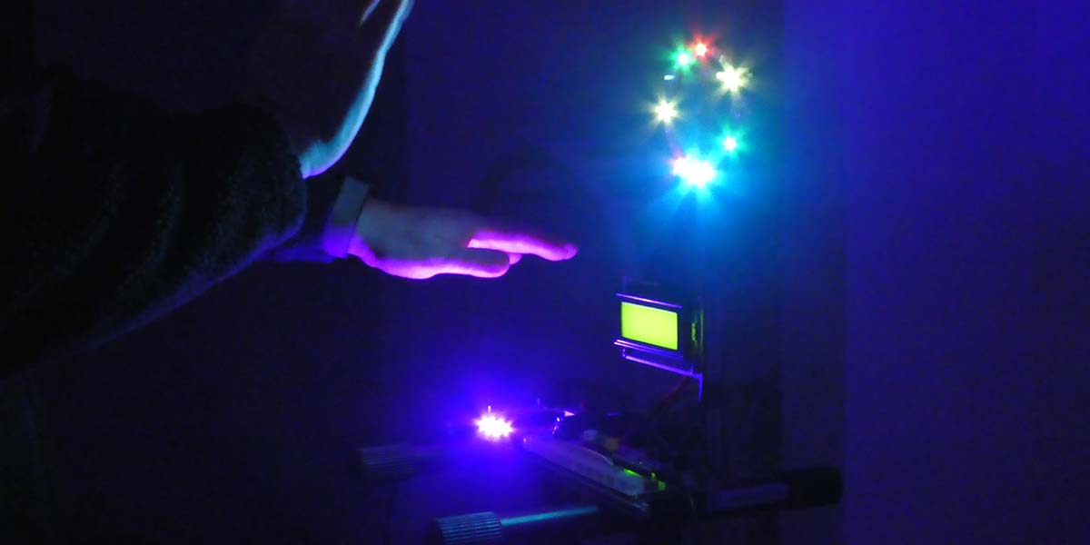
The current pitch is always indicated on the 24-element pitch LED ring. The 12 scale notes are situated on every other LED. When you're on a note, the corresponding LED will be illuminated in a light blue color. When you're between two notes, the LED between those two notes will be illuminated in orange.
As well as providing a truly outrageous amount of bling, this mechanism works surprisingly well. You can see if you're on a note or between notes, and this visual feedback combined with muscle memory makes the instrument quite playable.
Like any instrument, the LASERVox requires proper setup, a playing technique, and lots of practice in order to get the best out of it.
A crucial part of setup is the choice of voice. Obviously, this depends on your synthesizer, but there are certain rules of thumb as to what works well and what doesn't. You'll find that voices that have a sharp attack and immediate decay (pianos, harps, plucked instruments, tuned percussion, etc.) can be quite difficult to play. Because of the attack, if you hit a wrong note, it can be very obvious depending on what scale you're in. Also, because of the decay, there isn't that much scope for shaping the volume of the note with the left hand.
I find that any voice that plays until a key is released works pretty well, and voices that have a soft attack such as strings and pads work really well and are very forgiving.
Different scales have different degrees of playability, and some are much more forgiving than others. You'll find that the chromatic scale is the least forgiving, while the blues scale lets you get away with pretty much anything because you can't really play a wrong note. It's similar for the pentatonic scales as mentioned previously.
In terms of technique, some (but not all) Theremin technique can be applied to the LASERVox. If you're already a Thereminist, the LASERVox will present you with no difficulties. I list a few books on Theremin technique in the Resources section that make interesting reading. In particular, there's an excellent short section on basic technique in the Moog Theremini manual that you can download for free from the Moog website. I recommend this as a good place to start.
The Theremin and LASERVox require similar positioning of the instrument and player posture. The LASERVox should be placed such that the pitch sensor is in front of you at the same height and directly in line with your right shoulder. If you have constructed the instrument as I recommend, this puts the volume sensor in roughly the right place to be covered by your left hand. You can play the instrument sitting or standing, but you might find sitting easier at first.
With your right hand at shoulder height, close to your shoulder, palm outwards towards the pitch sensor, move away from the instrument until the lowest note begins to play. If you go a bit further away than this, the note will stop playing. This is the “auto off” feature of the LASERVox that means it doesn't play if the pitch sensor target is too far away.
The position of the lowest note establishes your base position. This should always be your starting position because if you want your arm muscles to learn where the notes are, you need to always start from the same base. If you now move your hand very slowly towards the pitch sensor, you should first see an orange LED as you move off the current note (it will probably flicker a bit), then the next note will sound and light up blue, and so on. You'll find all the scale notes at equal distances from the sensor.
I've spaced the notes out as far as I think is reasonable to make the LASERVox as easy to play as possible. If you find the volume sensor a bit of a stretch, you can reduce the spatial range of the notes by adjusting the global variable pitchMaxDist in the code. A smaller value compresses the range of the notes. You must always ensure that pitchMaxDist > pitchMinDist.
It's important with both the LASERVox and even more so with the Theremin to keep as still as possible, and only move your arms and hands. Relaxation is the key here, and this makes both the LASERVox and the Theremin very therapeutic instruments. When standing, I find it interesting how even small movements of my left arm changes my balance and can move me off (or on) to a note.
The LASERVox and Theremin differ greatly in terms of right-hand technique. A Thereminist can get a range of notes just by starting with a closed fist and slowly opening their hand. This works because the hand is acting as one plate of a capacitor embedded in the field of the pitch antenna. It's the whole body that controls the pitch; not just the closest part of the hand to the antenna. In fact, a good Thereminist can tune a note with a subtle movement of their head.
With the LASERVox, your hand provides the target for the laser pulse from the pitch sensor and everything further away than your hand is ignored. This also means that gestures may or may not be registered cleanly depending on where your hand is in the field of view of the sensor.
Generally speaking, I find a flat palm or a loose fist makes the most reliable target. Using your fist has the advantage that you can change notes by tilting your wrist, thereby moving your knuckles towards or away from the sensor. Left-hand technique is about raising and lowering your hand to change the volume. Holding your hand flat is probably the most robust approach for the LASERVox. The kind of dipping motions that Thereminists make probably won't work that well for you because the fingertips only provide a small target.
Always remember that with the LASERVox, it's the part of the hand nearest to the sensor that determines the pitch or volume. The actual shape the hand makes doesn't matter, as long as it presents a clear target. The LASERVox is a completely new instrument, and so that's all I can really say about its technique at this point in time. You can have great fun experimenting and finding your own way.
Going Further
I hope you enjoy your LASERVox and have fun playing it! Here are a few ideas of other things you can do with it:
1) Use the LASERVox as a general-purpose MIDI controller. You can change the Note On, Note Off, and Channel Volume messages generated by the sensors to any MIDI message you like. The LASERVox can be programmed to act as a type of “expression pedal” for a synth or to control parameters for a Digital Audio Workstation such as Apple LogicPro or Ableton Live.
2) Program some drum sounds and use the LASERVox as a set of “air drums.” Fun? Definitely! Useful? I wouldn’t know because I’m not a drummer.
3) Instead of programming scales, program short tunes or basslines.
4) Use the LASERVox to trigger samples. NV
Parts List
Full Size Solderless Breadboard
47R Resistor, two off
10K Resistor, three off
Tactile Pushbutton, (e.g., Adafruit #1009), three off
Parallax FLiP, SKU32123 (www.parallax.com)
Parallax LASERPing, SKU28041, two off
Parallax Serial LCD 4x20, Backlit, with Piezo Speaker, SKU27979
LED Ring, 24xWS2812 LEDs, (Adafruit #1586 or similar), two off
MIDI Out Socket: DIN 41524, 5/180 degree mini-DIN Connector, Right Angle, PCB Mounting (e.g., CUI, Inc., SDS-50J or SparkFun PRT-09536)
Micro-USB Power Supply, 5V, 2.5A (or greater). Do NOT use a USB charger!
MakerBeam Starter Kit https://www.makerbeam.com/makerbeam/makerbeam-10x10mm-profile-kits (optional)
Resources
“Parallel Processing with the Propeller FLiP,” Jim Arlow, Nuts & Volts
https://www.nutsvolts.com/magazine/article/parallel-processing-with-the-propeller-flip
“Build a MIDI Lyre” Jim Arlow, Nuts & Volts
“Build a MIDI Autoharp” Jim Arlow, Nuts & Volts
Grégoire Blanc and Orane Donnadieu playing “Clair de Lune” by Debussy. Astonishing!
https://www.youtube.com/watch?v=ZVue-QsxuzA&feature=youtu.be
Grégoire Blanc YouTube
https://www.youtube.com/channel/UCDMBgt3Hk4cPpUh7w-UBuCQ
Carolina Eyck, Thereminist
https://www.carolinaeyck.com
Carolina Eyck, Theremin Technique
https://www.carolinaeyck.com/method
Clara Rockmore, Theremin Technique
www.electrotheremin.com/claramethod.html
Clara Rockmore was the first Theremin virtuoso. Her recordings are available on the usual streaming services. Haunting and beautiful.
Moog Theremini Manual — Contains a useful introduction to playing the Theremin
https://www.moogmusic.com/products/etherwave-theremins/theremini#widget14
“Build the EM Theremin,” Robert Moog, Electronic Musician, 1996
https://www.cs.nmsu.edu/~rth/EMTheremin.pdf
Table of Scales and Modes
https://en.wikipedia.org/wiki/List_of_musical_scales_and_modes
Parallax Propeller FLiP
https://www.parallax.com/product/propeller-flip-microcontroller-module
Parallax LASERPing
https://www.parallax.com/product/laserping-2m-rangefinder
Parallax Serial LCD, 4x20
https://www.parallax.com/product/parallax-4-x-20-serial-lcd-with-piezospeaker-backlit
Parallax SimpleIDE Development Environment
https://learn.parallax.com/tutorials/language/propeller-c/propeller-c-set-simpleide
MakerBeam Construction Set
https://www.makerbeam.com
Totem Maker Kit — Looks like an interesting plastic alternative to MakerBeam, but I have yet to try it out.
https://totemmaker.net/product-category/makers-robotics-kits/page/2
MIDI Association
https://www.midi.org
Leon Theremin — A short biography
https://www.uh.edu/engines/epi3070.htm
“Theremin: Ether Music and Espionage,” Albert Glinsky, University of Illinois Press; Illustrated edition (2 Feb. 2005), ISBN: 0252072758. This is the definitive history of the Theremin.
“How Equal Temperament Ruined Harmony (and Why You Should Care),” Ross Duffin, W. W. Norton & Company; Illustrated edition (31 Oct. 2008), ISBN: 0393334201.
Downloads
What’s in the zip?
Code Files