I’m doing some work with legacy computer equipment and have written Basic software to control time and temperature in a high temperature kiln. I’ve used an old Compaq laptop (LTE Elite 4/40CX). I use the COM 1 port to control temperature and the LPT1 port to cycle the kiln on/off via an SCR.
Everything works great. I’m able to toggle the printer port pins via OUT commands. When trying other legacy computers, everything works except the printer ports don't respond to the OUT commands and remain in a high state. However, they DO operate the dot matrix printer indicating they are functional. My question is how do I gain control of some of the data pins and be able to toggle them high and low?
#2181
Jerry Sobel, R.Ph.
Las Vegas, NV
Please log in to post an answer.
Answers
Very old Legacy computers used different physical addresses for the LPT port. Try some of the other addresses. The most common ones:
- Logical parallel port 1: I/O port 0x3BC, IRQ 7 (usually in monochrome graphics adapters)
- Logical parallel port 2: I/O port 0x378, IRQ 7 (Addon I/O cards or using a controller built into the mainboard)
- Logical parallel port 3: I/O port 0x278, IRQ 5 (Addon I/O cards or using a controller built into the mainboard)
Note: More modern computers can require interrogating the OS or an interrupt call. Also a device driver may be required.
Steve
East Hartford, CT
This is great! The humble printer port lives! Here’s my guess as to what is happening in your situation.
You are using the OUT command and the syntax is OUT Port#, Data where Port# is the address of the parallel port, typically &H3BC, &H378 or &H278. You need to find the address for your particular configuration. In the older machines, the Parallel Port was on a separate plug-in card and there should be jumpers on the card for setting the address.
The reason why the dot matrix printer works is because the print routine in use calls for the data to be sent to LPT1: instead of the port address. The computer’s BIOS translates the LPT1: to your port’s address. You are bypassing this function by going directly to the port via the OUT command. You should be able to go into the PC’s BIOS setup and find the port address assigned to LPT1:, then use that address in your OUT command.
Or open up the PC, find the parallel port setup jumpers and set them so the port address matches the address on your Compaq. Note that if you do change the card’s address, you’ll probably have to go into the BIOS and make the change there too.
May I suggest getting hold of the book Parallel Port Complete by Jan Axelson? A veritable boatload of information, including an example program for identifying what ports are installed in Chapter 4.
Jerry McCarty
Jackson, MI
Do a Google search for partester by Kellyware (freeware). The information displayed and ability to toggle the outputs will give you the troubleshooting information you need. The program was created in support of the CNC program Kcam that uses the parallel port to control these machines.
Steve Benson
New Castle, IN
Depending on your computer, LPT1 may have one of two addresses. LPT1= 03BC hex, DATABYTE 956, STATUSBYTE 957, CONTROLBYTE 958 or LPT1= 0378 hex, DATABYTE 888, STATUSBYTE 889, CONTROLBYTE 890. Whichever one you are using, try the other one.
Dave Hogan
N Palm Beach FL
I would check the printer port settings in the BIOS. The LPT port should be set up for bi-directional communication. “Standard parallel” will not work. ECP should work. Different BIOSs have different options for the port settings. P. S. My dad and my brother were both pharmacists.
Bob Kottas
Omaha, NE
There are 3 types of printer ports for PCs, Standard, EPP and EC. Check out the Wikipedia article at https://en.wikipedia.org/wiki/Parallel_port There may be an issue with LPT1 not being at the address expected, see the Interfaces and Access sections. It may also be possible to use one of the DSR or DTR lines from the serial port to control the SCR.
Philip Martel
Salem, NH
Many eons ago I did something similar, using 80286 vintage computers to control a weather station via LPT1. The BASIC routine needed to know the address of the LPT port, which on my machines was always 888 (decimal). I do remember that Compaq machines used a different address, but unfortunately I can’t recall what it was.
I suggest you consider migrating your control system to an Arduino or Raspberry Pi platform. I have done this myself, and never looked back. The new boards are so much smaller, cheaper, less power hungry, more user friendly from the standpoint of hardware control, and there is exhaustive online support.
There is no need to buy a chip programmer or use assembly language. I have not been so excited about electronics since discovering solderless prototpying and integrated circuits 30 years ago.
Steve Turner
Labadie, MO
I’m building a lie detector based on heart rate, breath rate, and galvanic skin response. I have it all figured out except for breath rate. What sort of sensor should I use to detect breath?
#2183
Jeanne Villeneuve
Vidalia, GA
Please log in to post an answer.
Answers
This makes me think of the automotive MAF (Mass Air Flow) sensor.
Essentially it is a small diameter resistive wire suspended in the air duct. A small current flows through the wire, and is warmed up that way. The wire resistance will change (due to the cooling effect) of air flowing over it. So at a specific regulated voltage, and used in a breathing tube, the current will change depending on breathing.
It could possibly even distinguish between breathing in, and out (due to assumption that air going in would be cooler than air going out).
Bill van Dijk
Canada
You’ll need a strain gauge band to wrap around your subject’s chest and a detector that’ll take the (very small!) varying voltage generated by the strain gauge and turn it into something useful.
Ken Simmons
Auburn, MI
I’m trying to duplicate an ESP experiment described in the book “What A Plant Knows,“ by Chamovitz. Basically, I need an amplifier and sensor to read signals from stems and roots. What frequency response does the amp need? My guess is from DC to maybe 20 Hz? If this is the case, then what sort of amp configuration do I need?
#2182
Carlos Dixon
Flint, MI
Please log in to post an answer.
Answers
Mr. Dixon desires to amplify electrical signals originated in plant stems and roots. This is a perfect application for an instrumentation amplifier circuit. Instrumentation amplifiers amplify the voltage difference appearing between two sources, neither of which is referenced to ground.
Basic information on instrumentation amplifiers and lots of applications bulletins from IC manufacturers such as Analog Devices, Texas Instruments and Intersil can be found if the phrase “instrumentation amplifier applications” is used as an internet search argument.
Peter A. Goodwin
Rockport, MA
I have two desktop computers and three 32" HP Pavillion 32Q monitors being used by two people at the same time. One of the monitors is assigned to each computer and depending on the applications being used, the third one goes to whomever benefits most by having two screens. I have to physically disconnect and reconnect the third screen when it needs to be moved to the other PC.
How can I do this without having to crawl uder the table to make the switch? I've looked at KVM switches, but I only need to share the third monitor, not the keyboard, mouse, etc. The monitors use the display port input and run at 2560 x 1440. I would just add another monitor to run two with each PC, but there isn't enough room in the work area.
#1184
Vicente Benedetti
Athens, TX
Please log in to post an answer.
Answers
I have used a D-Link KVM to switch only the monitor. There is button on the front for switching. If you use the KVM to switch everything, you can use a keyboard hotkey for switching.
Bob Kottas
Omaha, NE
You can get displayport switch boxes that will do what you need, or you can simply use a standard KVM and only connect the video signals. The KVM doesn't care whether the keyboard and mouse signals are present.
James Sweet
via email
I have a newer HD LED television that does NOT have an S-Video input jack! My old VCR and tapes are all S-VHS, so I need a schematic for building a converter for S-Video to Composite if I want to watch my old family movies. Please help!
#1181
Henry Vaden
Whitestone, NY
Please log in to post an answer.
Answers
VHS tapes deteriorate and fail. The machine is unlikely to be repairable due to parts availability and even replacing the machine is major dollars. For family videos, you really want to keep, I would suggest converting the tapes to a more modern format say DVD or a standard video file format.
Modern PCs have an HDMI port that connects to your TV. You can buy hardware you can use to convert them to PC format yourself or contract a service to do it for you. You can buy an S-Video to HDMI converter if you want to go that way. I will say that my HD TV had issues with playing the tapes due to slight variations in the timing signals from the tape which caused blackouts and breakups in the picture. You may have better luck with your TV.
Steve
East Hartford, Ct
You need a composite video, left audio and right audio to HDMI adapter. I believe S-video is composite video/audio basically as a digital TV of new would see it. Search eBay or Amazon for it. You’ll need cables with those names too.
Dave
Grand Rapids, MN
If you go to Wikipedia.org and look up S-Video, there is a simple schematic for an s-video to composit adapter.
Russell Kincaid
Milford, NH
S-video carries the luminance (B&W picture) and the chroma (color information) on separate wires as opposed to composite video which mixes them together to be carried by a single wire. There are fancier ways to combine the chroma and luma signals but often you can get acceptable results by simply tying them together, most of the inexpensive S-video to composite adapter cables do just that.
James Sweet
via email
Larry Supremo
San Diego, CA
You can buy S-Video to Composite video adapters from amazon.com, walmart.com, newegg.com, monoprice.com, and brick and mortar places like Fry's Electronics, Best Buy and others. I've even seen one at Target.
You can get them as small adapters, boxes you have to plug cables into or even built into a cable, with a S-Video DIN receptacle on one end and an RCA plug at the other. Plug "S-Video to Composite video adapters" into google.com.
Stan S
West Hills, CA
Gary Manigian
Martinsville, NJ
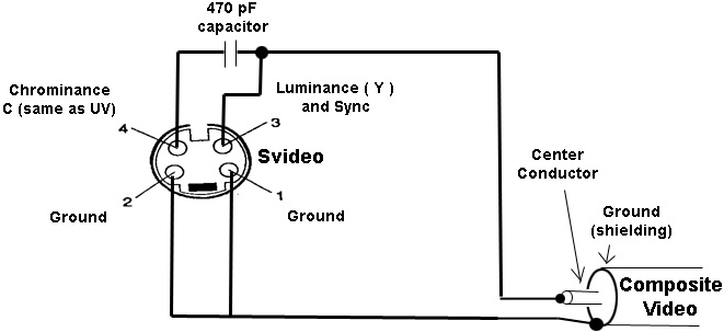
S-Video (also known as Y/C), refers to a video signal where the two components of the television signal (the sync and “luma” or “Y” which can be thought of as the black-and-white portion of the television signal, and “chroma” or “C” which includes the color information of the television signal) are carried on separate conductors inside a common cable. This is done to improve the quality of the television signal compared to a composite signal where the two components are combined and carried on a signal conductor.
Simple S-video to Composite adapters exist that combine the Y and C signals together with some capacitance and maybe resistance added for coupling and level-matching. Being that the required components are so small, they are often packaged together in an S-video to Composite coupling adapter or a short cable.
They are widely available and quite affordable. Two sources:
www.amazon.com/Electop-S-Video-Female-Composite-Adapter/dp/B01DKR7CAK
www.amazon.com/StarTech-SVID2COMP-S-Video-Composite-Adapter/dp/B0000BZ2WC
If you want to build your own S-video to composite converter, the following is a good place to start.
Y-ground—+ +— RCA/composite ground C-ground—+ Y—+ +— RCA/composite video C—||—+ 470pF
Note that going in the reverse direction is more difficult — using the adapter to convert composite video to S-video will result in a viewable picture, but the quality will be reduced due to the adapters inability to cleanly separate the “Y” and “C” signals.
Todd Efaw
Emerald Coast, FL
The answer to your S-Video problem is one that is easy. Go to Amazon.com and look at these converters.
StarTech SVID2COMP 6-Inch S-Video to Composite Video Adapter Cable $2.06 each.
Electop 2 Pack S-Video Female to RCA Male Composite Video Adapter $6.59 (Prime) for a pair (very small device that I have used for years).
But your biggest worry is your S-Video machine. Start looking at the converters to put your tapes on your hard drive and a backup on a Thumb Drive for safe keeping, if your home movies are not replaceable.
Good Luck and a healthy New Year to you.
Dave Wreski
Conway, SC
I’ve been eyeing 3D printers for a while, and there are now basic units in the $100 range.
However, it appears that software can cost between free and several hundred dollars depending on features and capabilities. I like free. Is anyone using free software to create and print using one of these low-cost printers? If so, which software and printer are you using that you would recommend? Any caveats?
#1183
Brenda Spellman
Green Bay, WI
Please log in to post an answer.
Answers
I am using Matter Control. By far this has been the easiest right out of the box. In most cases you do not need to go into settings, except to change resolution. When first installed you will need to enter type and print area of your printer. The only complaint I have ever had is there is no Emergency Stop. You can stop/pause the print, but in some cases you just have to kill the job. Good luck!
Todd Dragovich
Dothan, AL
I purchased my first 3d printer — the Tevo Tarantula — last February, and I have enjoyed every minute of it. The Tevo has a large support group on facebook (if you’re into that — I’m not) as well as on Thingiverse. I would also point you to Thingiverse to find dang near any model you could ever want — including a whole multitude of upgrades for the Tarantula. I myself have uploaded a few of my own modifications (my username there is ‘rebeltaz’).
The only drawback to low cost printers is that a lot of the controller boards are not able to properly handle the current required for a heated bed. You will want to get a MOSFET interface board — the cbd-3d being a popular model — to offload the current drain to a more suitable controller.
As for software, you are going to find diehard recruiters for all the available packages. Me personally, I prefer Sketchup for functional models, since I already had experience with that program. You will need to add a plugin called SolidInspector to ensure watertight (i.e. solid) models suitable for 3d printing. Another good free alternative I use is Blender. This program seems better suited for more organic models, although you can use it for functional designs.
If you lean towards “cloud based” software (I do not) there are various alternatives in that category as well — TinkerCAD being a popular one.
You will also need a slicer program whose job it is to generate the g-code understood by the printer from your 3d model. Simplify3D is a relative expensive example, but both Slic3r and Cura are excellent freely available alternatives. I personally prefer Cura due to it’s more user friendly interface.
Finally, (well, in closing anyway) I would also recommend that you think about getting a Raspberry Pi later on and load it with OctoPi. This will allow you to access and control your printer wirelessly from anywhere on your local network, or even around the world if you so desire.
If you ever have any questions or need any help/advice, I am always willing to help newcomers to this wonderful hobby. You can find me on Thingiverse. Hope to see you there!
Derek Tombrello
Shelby, AL
I have an old guitar “echo” pedal that is dead. After some troubleshooting, it appears the SAD1024 chip in the unit has given up the ghost and I have been unable to find a replacement chip.
Is there a substitute for it or a source for replacing it?
#1182
Mike Styles
Pennsauken, NJ
Please log in to post an answer.
I’m refurbishing a tube-type Hallicrafters shortwave receiver. I was planning on using a solid-state plug-in replacement for the rectifier tube; mostly because I can’t find the tube.
I’ve been told that a solid-state rectifier could result in higher voltage, and may blow the filter capacitors and run the tubes at a non-linear part of their operational curves. Can someone confirm or explain if this is a good idea or not?
#12174
Matthew Stiefel
Steelville, MO
Please log in to post an answer.
Answers
Vacuum tubes are resilient and can withstand over voltage better than solid state parts. Tube characteristics are dependent on the physical construction and don't change with voltage if the circuit is properly designed. If the radio has a power transformer, It certainly has a full wave rectifier. The 5Y3 has a tube drop of 60 volts so if it is replaced by a solid state rectifier, the DC output should be 60 volts higher. This is not significant when the nominal DC output is 300 volts. If you are worried about it, put a resistor in series.
Russell Kincaid
Milford, NH
The maximum voltage output from any rectifier is less than the peak voltage, so start from that end by measuring the RMS voltage of the AC power transformer output , and multiply that by 1.4 to get an average peak voltage. If it is less than the filter capacitor DC rating then you are safe to install any solid state rectifier that has a higher voltage and current rating. Anyway, replacing the filter capacitors is always a good idea due to aging.
Raymond Ramirez
Bayamon, PR
You might look at tubesandmore.com. They have thousands of vacuum tubes.
David Goodsell
Apple Valley, CA
Tube guitar amps use solid state rectifiers all the time, check out Mesa Boogie. I suspect they are more efficient, and the supply voltage may increase a bit, but my guess is that it’s not so dramatic as to destroy everything, maybe 10-20% increase.
If you can disconnect the rest of the receiver you can always try it and measure the before and after supply voltage, see if it’s still in a safe range. Be careful doing that, of course, it’s a high voltage power supply.
Ralph Hipps
CA
I think the filter capacitors are at a slight risk during the replacement procedure. But maybe they need replacement anyway.
First you need to know the existing rectifier output voltage, measured from a trial run or read from the instruction manual. Then you use silicon diodes to replace the tube rectifier. Re-measure the voltage and B+ current. Be careful these voltages can give you a memorable shock.
Then use Ohm’s law to calculate a resistor to put in series with the B+ line to return the B+ to near its original value. Don’t forget to calculate the power dropped by the resistor to make sure to get one of sufficient dissipation (watts) rating.
If you are uncomfortable with these steps, get a ham old-timer to help. The good side is you should improve reliability and save the power that went into the rectifier filament.
Chip Veres
Miami, FL
I would say it's a bad idea. Solid state rectifiers have a much lower internal resistance than tube rectifiers, resulting in significantly higher voltage. I'm surprised you can't find a replacement. What's the tube you need?
Steve Rohrer
Decatur, GA
A solid state replacement will have a lower forward voltage drop than a tube, typically less than a volt. So, the rest of your circuitry will see a few extra volts. This is not likely to be a problem, however I would have another concern.
Using a solid state rectifier means that it will begin rectifying immediately upon power up, the rest of the tubes will NOT yet be conducting and therefore the entire circuit will be drawing very little current. This means that your power supply caps etc. will probably be seeing close to PEAK voltage until the tubes begin to conduct and draw current.
When using a tube rectifier; it too comes up slowly as the rest of the tubes do, you do not get the PEAK voltage anywhere. I’d stick with the tube rectifier; eBay and lots of other on line suppliers can get you one.
Bob Morris
via Internet
In regards to your rectifier tube for the Hallicrafters Radio, I suggest you have a look at this website: https://www.tubesandmore.com/products/vacuum_tubes?filters=Type%3DRectifier
They have all kinds of older tubes, most are what is called New Old Stock. We could have provided more information as to use of a solid state rectifier replacement, but it would have helped to know the radio model number and the tube number you were replacing. Hope this helps you fix it.
Bruce Bubello
ARS WA2HWV
A solid state rectifier will have less than a voltage drop, a tube is higher depending upon the tube and the current level, etc. This will result in a somewhat higher voltage to the circuitry, but not an awful lot.
There is, however, another situation to consider. When you power up with all tubes, they all come on slowly. Tubes begin to conduct plate current as the rectifier begins to work, sort of a “soft” start. With a solid state rectifier, it will begin immediately upon application of power, while the tubes are not yet consuming any current as they warm up.
This means that since drain on rectified supply is quite low until the tubes come up to speed, the power supply caps will charge pretty much to peak levels, which may exceed their ratings, or certainly stress them more than if you were using a tube rectifier.
I’d suggest sticking with a tube rectifier. You should be able to get one via eBay, or many other on line sources.
Bob Morris
Pennellville, NY
Also, a solid state diode has no warm up period. It means that full power supply voltage instantly is present on a circuit that may not be ready for it yet. It can be done, but replacement of a tube with a solid state diode may need some additional precautions (a heavy resistor in line may be enough). I say may, since there are definitely sets which are capable of absorbing this difference.
Most Hallicrafters sets were not the most rugged out there, many without the safety of power transformers. I’d be careful. On the other hand, I find it hard to think you would not be able to find a suitable tube on FleaBay or some of several tube vendors on line (Try Antique Electronic Supply).
Bill van Dijk
Carp, ON CANADA
You are correct in that there can be some issues to be considered when replacing a tube rectifier with a solid-state replacement. The primary issue is timing. A solid-state rectifier will provide the full B+ voltage almost immediately, while a tube rectifier needs to have the filament warm up, and the B+ voltage will come up much more slowly. Also, the other tubes which will use the B+ will need to warm up and be able to provide a suitable load for the B+. Without a load, the resistors in the supplies will not drop voltage as intended, and so the voltages at the plates of the consuming tubes will be much higher initially until those tubes warm up.
In addition, the tube rectifier has a “resistance” providing a voltage drop that the solid-state device will not. This means that the output of the power supply section will be at a higher voltage than that with a tube. The capacitors must be rated to handle the increased voltage, and the circuit will need to operate properly with the increased B+ voltage.
If the radio has not been operated in some time, it would be good to replace the filter capacitors at a minimum. Some solid-state replacements will include some internal resistors and thermistors (resistors that change value as they heat up) to approximate the characteristics of a tube rectifier. This type of replacement is usually best.
After installing the replacement, the B+ voltage should be checked against the normal expected voltage, and perhaps some of the resistance values in the power supply can be adjusted if needed.
George Kaczowka
York, ME
AMP Clamp
Answered
December 2017
Could someone explain in simple terms how an AMP clamp works? Does it have a transformer in it or Hall-effect sensors or similar?
#12172
Kevin Champion
Cleveland, OH
Please log in to post an answer.
Answers
There are two major types of clamp on current meters. The AC type is a transformer; the wire in the clamp is the primary, the secondary is internal and is normally 1000 turns. If you are measuring 100 amps the secondary output will be 100 mA. The other type measures DC and could be calibrated for AC. The DC type uses a hall-effect or similar sensor. Amazon lists an AC/DC meter for $39.
Russell Kincaid
Milford, NH
Most clamp-on ammeters use a transformer located inside the body of the meter to step-up the measured current to a value which the unit can use.
Jeffrey Massey
Columbia
The common AC current meters use a transformer to measure the current. The “clamp” is the core for that transformer, and it is opened to go around the AC wire as it becomes the one-turn primary. There are simple components to scale the multi-turn secondary current down for the correct reading, either analog or digital. The digital part uses its own circuit to convert the measurement to its display.
A DC current meter cannot use the same transformer method, so it uses the Hall device that converts a magnetic field to a resistance, and the internal components convert that resistance to a reading, analog or digital.
Raymond Ramirez
Bayamon, PR
You are on the right track. The ones that measure AC use a pickup coil, and the ones that measure DC use a Hall effect sensor.
Chip Veres
Miami, FL
An AMP clamp is a transformer having a one-turn primary (the conductor carrying the current to be measured) and a multi-turn secondary (to feed the measuring instrument).
Being a transformer, it can only be used to measure alternating current. Be aware of its measurement rating, because too much current can saturate the clamp, resulting in inaccurate readings.
The clamp is rated for sinusoidal currents: measurements of non-sinusoidal current is best done with a true-RMS instrument connected to the clamp secondary winding.
Currents small relative to the capability of the clamp can be measured by passing the conductor through the clamp multiple times and dividing the measured value by the number of turns.
Peter A. Goodwin
Rockport, MA
AC amp clamps use a current transformer. The clamp is a laminated iron ring with a coil of wire wound around it. The alternating current in a powered AC line induces a magnetic flux in the clamp’s ring which the attached coil picks up via electromagnetic induction. That induced signal is fed to an amplifier who’s output is rectified and filtered and the resulting averaged (i.e. RMS) DC voltage is fed to the meter’s measuring circuit. The typical conversion is 1A AC = 1V DC on the meter.
DC clamps use Hall Effect sensors. As I understand them, the construction is similar to AC clamps, except an exciter coil is attached to the iron ring to pre-energize the ring with a specific frequency/voltage, which the Hall Effect circuitry sees as a zero level. DC current flowing through the clamp creates a magnetic field which alters that excite signal, which in turn changes the signal the Hall Effect sensor sees, which causes the Hall Effect detector circuit to output a voltage (positive or negative) proportionate to the current flowing in the measured conductor. Like the AC clamp, that detected signal is fed to an amplifier which outputs a DC level which is fed to the meter’s measuring circuit with a similar conversion scale (i.e. 1A DC = 1V DC on the meter).
As you’re aware, amp clamps are an EXTREMELY SAFE method of measuring high current (i.e. 10’s and 100’s of amps) in powered circuits because you don’t have to break any wires for making the measurement. HOWEVER, because their resolution is typically between 100 mA (0.1A) and 1A (due to the limitations of the magnetic detection circuitry), amp clamp’s use is limited to measuring power lines connected to large devices (i.e. pump motors) that naturally consume large amounts of current in operation.
Ken Simmons
Auburn, WA
VGA To LCD
Answered
December 2017
I would like to be able to drive a 4x20 line LCD with a VGA output from an old computer. Is there a simple interface to do this?
#12173
Evan Lee
Elizabethtown, IL
Please log in to post an answer.
Answers
The short answer is no. VGA is an analog interface, LCDs use a digital interface. You would need a 3 channel ADC to start with, but even that’s not enough. It would be very difficult to extract alphanumeric characters for the LCD from that data. Plus the 4x20 LCD is so small compared to the VGA display that there’s no way it can hold all the information shown on VGA.
You would be FAR better off rigging up some kind of serial port interface to the PC with the VGA output and selectively sending whatever data is of interest to the LCD.
Ralph Hipps
CA
In all honesty, I believe this would be a fruitless exercise. The interface would be far from simple, and the resulting image on the 4x20 LCD display would most likely not be recognizable from the original VGA image.
VGA has a resolution of 640 x 480 and the LCD display would be 100 x 28, assuming 5 x 7 matrix for each character. Keep in mind the LCD display consists of a 4 rows of 20 characters each. Each character is formed by a 5 x 7 dot matrix, and the characters are separated by approximately a pixel width and 0.2 pixel height. So you are going from an aspect ratio of 4:3 to 25:7 or 12.5: 3.5, a significant difference.
In addition the pixels in the VGA display can vary in color and brightness, where the LCD display is only black and white, and are not individually adjustable in brightness.
And finally, the electronic interfaces to drive each type of display are significantly different both in hardware and software, and would require a very complex interface to even come close.
Ira Wexler
Owings Mills, MD