I have a 100 amp 110 volt DC generator. I want to convert the output to 60-cycle AC. Does anyone have a schematic or info to build a converter? How much power loss can I expect in the final converted output? Thanks for any info.
#1191
Lucio Saunders
Indianapolis, IN
Please log in to post an answer.
Answers
You don’t need a converter. You need an inverter. A converter is used to change AC into DC or DC of another voltage, while an inverter changes DC to AC. That being said, there are many ways to skin this cat, depending on how much you want to spend and what you want to use the AC output for. Before we go there though, we have to start with basics: the generator.
In your question, you did not specify the type of DC generator that you have or how you are driving it. There are three types: the shunt; the series; and the compound. Each has its own set of operating characteristics. I assumed that yours is of the shunt type, the most common. The Rheostat (R) is used to adjust the output. The voltage (E) and current (I) are monitored and the output is supplied through a 125 amp fuse.
Your generator is rated for 100 amps at 110 volts which is 11,000 watts (11,000/750 = 14.67 horsepower). Add 20% because no generator is 100% efficient, so about 18 horsepower is required to drive it at its rated speed. This is important because the output of a DC generator is related to both its field strength and operating speed.
There are three ways to do what you want to do.
The first option is the simplest — just use a 110 volt DC to AC inverter. These are around because they were once used on small hydro electric systems. You may be able to find one on the Internet, but I don’t recall any being large enough to handle 11,000 watts.
The second option is a bit more radical, but much more feasible as the inverters are widely available for usage in the alternative energy field. A pair of 48 volt magnum energy MS4448PAE inverters are connected in series and these are in parallel with a pair of series connected high-value capacitors. An equalizer line runs from the junction of the capacitors to the junction of the inverters. This works because these inverters like to operate around 55 volts and because their outputs are in parallel, they share the load evenly. The equalizer line is a safety to handle any imbalance.
As for output, these inverters are rated for 4,400 watts continuously, 4,800 watts for 30 minutes, and 6,000 watts for 30 seconds. The first two specifications are all that matter in your application. Assuming 90% inverter efficiency, the generator will supply 9,680 watts (88 amps) to produce 8,800 watts of AC. The generator will supply 10,560 watts (96 amps) to produce 9,600 watts of AC for 30 minutes at a time.
The third option is the most radical, but it allows two things the other options do not: redundancy and the ability to supply AC to the utility grid. This option utilizes microcontrollers commonly used on photovoltaic modules to convert low voltage DC into 60 Hz and then to synchronize this to the utility grid. I have chosen the Enphase Energy 250 watt unit. You will need 36 of them and they are used in groups of three to allow an input of 48 to 144 volts. This is well within the range of your generator.
The outputs of all the units can be connected together to produce about 9,000 watts of AC power at 120/240 volts or they may be connected for three-phase output at 208/120 volts. They must be connected to the AC grid to operate though. By having 36 units in 12 series strings, the failure of a single unit will only reduce the output by a little more than 8%. It was nice talking about the good ole days of DC. If you have any other questions, you can contact me directly at PO Box 9106, Concord, MA 01741.
Craig Shippee
Concord, MA
There are a number of articles in the past issues of Nuts & Volts for a variety of ways to control devices in a home using a variety of control devices and schemes. However, none seem to have the combination of characteristics that I want. I would like to control a pair of simple low current AC sockets (ON/OFF) from my cell phone. I would like to use a combination of an existing app, a PIC style device (Ardunio or whatever), and a Wi-Fi module to connect it to my existing Wi-Fi. I do not see why a $100 hub should be needed. My present cell phone uses the Windows operating system, but I know that apps for it are scarce and I am willing to get an Android device. I’m stuck on finding the cell phone app and the Wi-Fi module. I would assume that I would have to write the appropriate code for the PIC device. I can interface the PIC with a relay, probably a solid state one. Any suggestions?
#3193
Edward Alciatore
Beaumont
Please log in to post an answer.
Answers
If all you want to do is to be able to remotely control an AC outlet via a mobile device from anywhere, then simply buy a WEMO Mini Smart Plug. These are sold in Home Depot for about $25. They connect to your home WIFI, are very easy to install and have APP’s for both Android and Apple IOS devices.
These Smart Plugs have a switched AC outlet capable of carrying up to a 15A load. No code to write, nothing to build, just download the APP, plug the WEMO Smart plug into any AC outlet, follow the APP instructions and you’re up and running in five minutes. Install as many devices as you need remotely switched outlets.
Roger Baker
Redmond, WA
The easiest way to do this would be to buy some TP-Link KASA modules. No hub required — just plug them in, load the app and in a couple of minutes you’re done. AND, they work with Alexa/Google Home.
Bruce Robin
Naples, FL
Sonoff makes a bunch of home automation wifi devices. I have several of their products which I got off Ebay and AliExpress. Just type “Sonoff” on the search line. They do a lot more than just switch devices on or off. I paid about $6 for a single channel and about $15 for a 4 channel. Rated 10A @120VAC.
Simple to setup, the device just needs to be within range of your router. The free app is only available for Andriod/Apple phone, although they say you can use a PC if you run it thru an “Android Emulator” program. Never tried this though.
Harold
Rochester, NY
My brother has an old MG that he likes tinkering with. He wants to use the side lights to indicate when the turn signal is on for drivers that are on either side of him. Normally, the side lights turn on and off with the headlights.
In his case — and to reduce peak power consumption to the blinker circuit — he would like the side lights to turn on when the signals are off, and vice versa (when the turn signal switch is turned on). Additionally, if the lights are on, the side lights should give priority to the turn signal, turning on and off, opposite to the signals in the front and rear, and returning to full on when the turn signal is not engaged.
I think the simplest way to do this would be with solid-state relays and the use of some logic gates (for each side). I have built hundreds of logic circuits, but have not really dabbled much in automotive applications. I know the electronics have their own temperature and performance specs and are noisy environments, not to mention the notoriously bad reputation that English cars have for electrics. Can you recommend a circuit for this application? (This car is a NEGATIVE chassis).
#3192
Patrick Gilmore
Amherst
Please log in to post an answer.
Answers
This is what we do in the DeLorean community for a similar effect. We also have a negative chassis but our side markers are not grounded to the chassis, but rather through their own separate wire. I am not sure how an MG does this. If the MG side markers are grounded through the chassis, perhaps you could find a suitable socket with two separate wires. Maybe also switching to an LED if wanted/needed.
Simply disconnect the ground wire of the side marker light and connect it to the positive side of the parking lights.
When the parking lights are off, the side marker will flash in sync with the turn signal lights, using the parking light bulb as a ground path.
When the parking lights are on the side marker will light up, using the turn signal bulb as a ground path and blink off, ie. out of sync, with the turn signal.
Dave Delman
Jericho, NY
Solid state relays are not ideal for this application. Automotive relays are cheaper, handle more current and are designed for the environment.
A 4 pack of automotive relays including the wiring harness from Amazon (for $9.97) will do what you want: https://www.amazon.com/Pack-EPAuto-Relay-Harness-Bosch/dp/B072QXDZRD
The diagram shows the wiring for the left side only. You need to duplicate it for the right side. RY1, when energized by the turn switch, gives priority to the turn signal. RY2 allows the side lights to light when the turn switch is on and the turn bulb is off. When the blinker turns the turn bulb on, the side light turns off, and vice-versa.
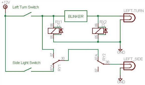
Add a 1N400x diode across each relay coil as shown in the diagram.
Ed
via email
I have wired many cars this way as car makers also do this on some models.
The side light can not be grounded. I have replaced the sockets in the side makers to a 194 bulb socket available at all auto parts stores.
In the day time, the side lights alternate blinking with the turn signals and ground through the filament of the park bulb.
At night, the side lights come on with the running light, flash opposite the turn lights, and ground through the turn light filament. (when park and turn are both on you power on both sides of the side light).
You can see this on many cars and trucks at night when turning, if you are observing things at night. I have also done this at rear of car when possible.
Only a special part may be a side light socket. If it’s a bayonet type socket, it has to change to a 194 insulated socket that is readily available.
John Obenchain
via email
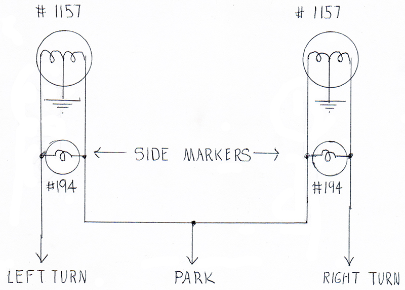
My 1988 Dakota has side lights like that. They’re just 194 type bulbs (you could use something like a 721 if you wanted really bright), connected across the turn signal hot and the parking light hot.
When the parking lights are off, you turn the turn signal on, the current flows through this bulb, then through the parking light filament, and it lights up. When the parking lights are on, and the turn signal is off, current flows from the parking light lead through the turn signal filament and the bulb lights up. When the parking lights are on, AND you have the turn signal on, both leads are at the same potential, and the light turns off. This will be complicated by LEDs, but for incandescents, it’s bog cheap, bog simple, and does what you’re asking for.
Ralph Phillips
Bossier City, LA
A local STEAM program is looking into using an RC car or truck to simulate operating a vehicle on the moon or other astronomical object. One big opportunity to excel is introducing a time delay (say five seconds) into the steering system to model the time required for radio to go signals to and from the vehicle. The first thought is to buffer the command string at the transmitter or receiver. Ideas, hints, suggestions?
#3191
Jon Caples
Parker, CO
Please log in to post an answer.
My cable system needs frequent resets. That means turn the power off to the cable box (router) and to my own WiFi router, wait 30 seconds, and turn the power back on. This is really aggravating when I am in the bedroom or the garage shop trying to watch streaming video on my TVs there and the routers are at the other end of the house.
I want to build a WiFi based system so I can activate a control to cycle the AC or DC power from anywhere in the house either via one of my computers or my cell phone. Now, my phone is a smart phone, but not a name brand like Apple. It’s a Nokia and uses the Windows operating system, so the available apps are somewhat limited.
So, I’ll need an app that will work there and one that will work on my desktop computer running Windows 10. I would like some ideas on how to proceed. I would think that I could base this on an Ardunio or other single board computer which could easily handle a 30 second time-out.
I can figure out the interface to the power relay, some local PB controls, and a display. But how do I handle the controls through the WiFi? I need advise on a WiFi interface and the apps that are needed to activate it.
#03191
Edward Alciatore
Beaumont
Please log in to post an answer.
Answers
The problem with your premise is that if the router and cable modem are not working (hence no internet or WiFi) how will you use WiFi to trigger the reboot?
The first thing I’d do is get to the bottom of why you need to do such frequent reboots. Is it the cable modem or the router that’s causing the issue? Personally, I’ve found cable modems from the ISP to be problematic. You’re probably paying $10+ tax a month to rent it when you can buy your own for under $100 - that’s a 10 month or less payback!
How old is your router? Best to use a router with gigabit ports if your streaming HD videos. As we started doing more streaming I also found that using gigabit switches improved performance dramatically particularly with ten IP security cameras running. I do use my router’s auto reboot feature nightly as we travel a lot but, unless the cable company has had an outage, I never have to reboot the modem.
Bruce Robin
Naples, FL
This may not be what you're looking for, but I've installed a metric boatload of these units for remote control of WiFi systems at banks and hotels. https://www.amazon.com/POWER-SWITCH-WLCD-SCREEN-OUTLETS/dp/B00EZWD146?ref_=fsclp_pl_dp_2
What you can do to make it even easier is set it up downstream of the router and modem, and have it ping something like, say, Google's DNS servers every 30 seconds. If it doesn't get a response, wait for up to 5 failures, then power cycle both outlets. You can also web browse to the interface, and hand cycle both; this supposes that the WiFi isn't built into the router (which if your main access point IS built into the router, you won't be able to turn it back on via WiFi anyway!) This is not the only way to do it; but it's one that works and is solid and reliable.
Ralph Phillips
Bossier City, LA
Is there a way to vary the speed of a music CD player? I play my instruments along with the recordings and need to vary the pitch slightly to match the tuning of my instrument. We used to do this easily with vinyl by varying the speed of the turntable.
#11188
Klaus Herman
Raleigh, NC
Please log in to post an answer.
Answers
CD players for professional/DJ market have variable pitch built in.
Erik von Seggern
Escondido, CA
I would be surprised. CD players are designed to KEEP their speed. I would convert the song to one of the usual audio file formats (mp3, wav) and run it on a computer with the free audacity tool. That lets you change the speed and even allows you keep the pitch! (Effect -> Change Tempo; Effect -> Change Speed). I use audacity constantly.
Werner G
via email
Could someone explain what pull-up and pull-down resistors are, when and how they’re used, and how to calculate their values?
#11187
Andy Dietrich
Dallas, TX
Please log in to post an answer.
Answers
Resistors are used in a number of roles in circuits. The terms “pull up” and “pull down” are used to describe two of those roles. A somewhat precise statement of the definition of a pull up resistor would be that it is a resistor where one side/lead is connected to a circuit device, often a transistor or FET or other active device, and the other side/lead is connected to the positive power supply voltage used for that circuit. Thus, it is trying to “pull” the terminal of that device “up” to the level of that power voltage. A “pull down” resistor would be the same idea but with the negative power supply voltage or ground in place of the positive one.
Active devices, like transistors, can be modeled as a variable resistance that is controlled by the base current: the greater the base current, the lower is that effective resistance (emitter to collector). So more base current equals more current in the emitter-collector circuit. But that, by itself, is not very useful in most circuits where an amplification of the voltage is what is needed. By adding a “pull up” or “pull down” resistor, depending on the polarity of the transistor and the arrangement of the circuit, a voltage divider is created. That voltage divider consists of the fixed resistance of the “pull up” or “pull down” resistor in series with the variable resistance of the emitter-collector path through the transistor. The output voltage is taken at the junction of the resistor and the transistor. That is where the variable current is converted to an amplified voltage.
The idea is pretty much the same with FETs and other active devices. “Pull up” and “pull down” resistors are also used with switches. The resistance of the switch is also variable: either zero or infinite. In that case the resistor will pull the output of the switch all the way to either the positive supply voltage or to ground.
The values of the “pull up” and “pull down” resistors are usually calculated with Ohms Law. The circuit designer must have a value for the current that will flow in the resistor/transistor circuit. There will be several concerns for that value including the load impedance, the current rating of the transistor, the desired point of operation on the characteristic curves of the transistor, the amount of quescient current that is allowable/desirable, and others. Once that current value is determined, it is combined with the supply voltage in Ohms Law to find the value of the “pull up” or “pull down” resistor. R = E/I
If the current is significant a calculation of the power dissipation in the resistor should also be made: P = VI where V is the supply Voltage and I is the maximum current that can flow in the resistor. A general rule is to use a resistor that is rated at two times the power level that this calculation produces as a safety margin. Often (usually) the resistance value of the “pull up” or “pull down” resistor is made as high as possible in order to avoid the use of high power resistors.
Edward Alciatore
Beaumont, TX
Pull-up or down resistors does not refer to a type of resistor, but its function. Usually their purpose is to give a high impedance wire a known state. For instance, an output pin on a MPU may be an open collector output, capable of sinking a few mA. When it is activated, its state is grounded. When released, it floats, and has no definable state. In this case a pull-up resistor connected to the supply line would give it now a high level.
Pull-ups and pull-down resistors can be used in many locations, another example would be in an I2C buss. Read up on that, most descriptions will do a good job of explaining how it works.
Bill van Dijk
Carp, CANADA
The basic idea of a pull up or pull down resistor came from some logic families which had output pins connected to the collector of the output transistor stage. There was no internal connection to a power supply, so the output did not respond to logic states if no other connection was made. A suitable resistor was tied to the plus supply, so when the base of the transistor was held low the output went to the supply voltage (pulled up to the supply), and when the base of the transistor went high it would pull down the output to ground. The open collector allowed outputs to be wire ORed together saving parts. By connect several outputs to the same resistor, if any of them them went low it would pull the resistor down (an OR situation).
Values for these are usually suggested in the data sheets for the parts. To calculate a value get the max output current from the data sheet and use your supply voltage and ohms law to compute the smallest allowed resistor.
The idea has been extended to resistor networks which aid in driving high speed signals through long lines. A google on impedance matching and line driving will get you started on this variant.
Warren O Wilderson
Eagle Point
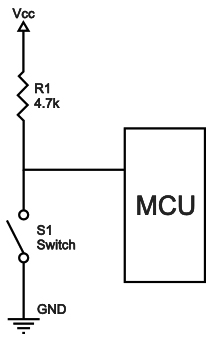
Pull-up and pull-down resistors once baffled me, too. Very often a device, say a 555 timer, will require a ground pulse to start a timing cycle. This means that one might install a momentary switch to ground to activate the timer. Well, if that pin on the chip is not already in some known state, it can behave differently each time it’s powered up. It may work as designed, it may not. If the wind blows from another direction, it may behave differently because it is “floating.”
Now, you could just connect it to the voltage that’s supplying the chip, but if you then forced that to ground, you’d have a short circuit and something is going to burn. If you have something held to supply voltage, say 12 volts, by way of a 10k resistor, it will sit there seeing 12 volts. If you then press the momentary button, the subject pin will see it as a ground and the 12 volts will cause 1.2 mA to flow momentarily.
So, you don’t have a short, the activating pin sees a ground pulse and starts working, and you won’t damage your circuit. Leaving any pin, even ones that specify “NC” (no connection) floating, may yield unexpected behaviors and not always the same “unexpected behavior.” In this case, it’s good practice to ground pins labeled “NC” either directly or by way of a “pull-down” resistor. If you always use a resistor, you minimize the chance of a short circuit even if you made a mistake in grounding the wrong pin. Hope this helps!
Brendan Ames
Albuquerque, NM
A pullup/pulldown resistor resolves a voltage ambiguity that may exist on a circuit node. These resistors are commonly used with transistors in digital switching operations.
A pullup resistor connects a node to logic 1 voltage (eg 5V) and a pulldown connects to logic zero (ground). For example, a bipolar transitor used for digital switching has a pullup resistor connecting logic 1 voltage to the collector node, i.e. the transistor switch output. When the transistor is off, no current flows through it or the pullup resistor. Ohm’s Law shows there can be no voltage drop across the resistor, hence the voltage on the collector must be at logic 1. When the transitor is on, current flows through the collector and pullup resistor. A voltage drop now exists across the resistor causing the collector voltage to drop below the level of logic state 1. The more current that flows, the bigger the voltage drop.
When a component is specified as open collector, the designer must supply the pullup resistor. This is the case for the I2C communication interface. The designer may choose a large pullup resistor to limit current and extend battery life. But there is a trade-off due to unavoidable stray capacitance (C) at the output. A large resistor will increase the RC time constant and slow down the response.
Mike Hasselbeck
Albuquerque, NM
Pull-up and Pull-down resistors are used to force an input signal line to a default level when there’s no external input applied. Typical pull-up values for Digital lines are between 1Kohm and 10Kohm, connected between the V+ line (i.e., +5 VDC) and the signal line. Pull-down resistors do the same thing, except they’re connected between V- (or GND) and the signal line, and are usually no smaller than 4K ohms.
To calculate the resistor size, you need to know how much current is going to flow INTO the line (pull-up) or flow OUT OF the line (pull-down). You typically don’t want more than 20 milliamps of current flowing through a pull-up nor do you want more than a few milliamps flowing through a pull-down. For +5V logic, pull-ups from 1K to 4.7K are sufficient. You rarely see pull downs with +5V logic, but they are needed sometimes. The power rating of the resistor is calculated using the (I^2) x R, and rarely goes above ½ watt.
You can connect a pull-up and pull-down in series, with the resistor junction connected to the signal line to form what’s called a receiver. You’ll typically find these on serial communication lines where the SIGNAL LOW value is a negative voltage. The pull-down resistor will usually be sized with the pull-up to create a voltage divider. You can find dividers with CMOS and +3.3V logic where you don’t want the HI to go above a certain value nor the LOW to go below 0V (GND).
Here is a good reference: http://www.resistorguide.com/pull-up-resistor_pull-down-resistor/.
Ken Simmons
Auburn, WA
To begin with, positive voltages are considered ‘up’ and negative voltages are ‘down’. A resistor connected to a positive voltage on one end and to a circuit element on the other end will be pulling the circuit element up to the positive voltage, if there is no current. If you want current to flow, you must figure how much and compute the resistance from: R=V/I; where V is the voltage drop across the resistor. Pullup resistors are often used with an IC that has an open collector output.
Pulldown resistors are most often used on the emitter of an NPN transistor. If the base of the transistor has a positive voltage applied, the negative voltage could be zero (ground). In any case, you need to know something about the circuit to compute the resistor value.
Russell Kincaid
Milford, NH
Good Timing
November/December 2018
I have an old model automotive timing light that attaches between the #1 spark plug and wire. How can I make an inductive pickup to sense the signal so I don't have to detatch the wire? Is it even worth trying to
#11186
Ricardo Stewart
Hanover, MD
Please log in to post an answer.
I want to build a backup proximity detector like many newer cars have, as a fun, useful project. The type that beeps in reverse when something is behind my car; faster beeping means the object is closer. I'm new to electronics, and I need help designing the circuit. I thought of using the PING))) sensors available from Parallax to sense the distance to objects. Any help with the circuit is welcome. It would be preferred to have it auto-activate when in reverse, but I could just as easily flip a switch mounted next to the shifter to activate if it becomes too complex.
#11185
Gregory O'Rourke
Newark, NJ
Please log in to post an answer.
Is there a device that will continuously "listen" to audio (via a mic or an earphone jack) and allow the user to push a button so that the device will repeat the last 20 seconds of what it just heard? I listen to scanners and ham radios, and often miss what was just said, and would like to get a repeat for clarity. I prefer a stand-alone device to an app or computer software.
#11184
John C
Montague, MI
Please log in to post an answer.
Answers
A company by the name of Nuvoton makes a chip that records sound — voice if microphone connected — which can then be played back with the push of a button. The chip is ISD 1964 for 64 secs of recording in various lengths of time segments. This is a surface mount 28 pin SOIC package and can be soldered nicely with a fine tipped soldering iron. You can find the data sheets on Digikey.com. I also recommend Onstate Technologies (OnstateTech.com).
They make a good quality circuit board for the sound chip and has room for most of the needed other components (thru-hole) including a version with an audio power amplifier chip to drive a decent speaker. I believe that the chip can be operated directly from a few push buttons. (Record, stop, playback). It can also interface with a microcontroller.
Robert B.
Calgary, Canada